Rotor and rotary electric machine containing the same

a technology of electric machine and rotor, which is applied in the direction of dynamo-electric machines, magnetic circuit rotating parts, magnetic circuit shape/form/construction, etc., can solve the problems of increasing the volume and cost reducing the output power and efficiency of the electric machine, and increasing the price of rare earth materials. , to achieve the effect of increasing the original volume of the electric machine and extending the output power of the electric machin

Inactive Publication Date: 2013-05-30
DELTA ELECTRONICS SHANGHAI CO LTD
View PDF3 Cites 21 Cited by
  • Summary
  • Abstract
  • Description
  • Claims
  • Application Information

AI Technical Summary

Benefits of technology

[0026]To sum up, in the rotary electric machine provided by the invention, axial magnetic steels are installed at two ends of the rotor core, so that the air gap flux density may be improved and the output power of the electric machine may be enlarged without increasing the original volume of the electric machine.

Problems solved by technology

However, currently, the price of rare earth materials is rising; and therefore in order to reduce the cost, it is expected in this industry to use permanent magnet materials (such as ferrites) with weak magnetic properties but low price to replace the neodymium iron boron.
However, since the remanence of the ferrite material is only 0.2-0.44 T, and the maximum magnetic energy product thereof is only 6.4-40 kJ / m3, a simple replacement may cause decrease in output power and efficiency of the electric machine.
However, these methods result in the volume and cost increase of the electric machine.
However, this structure can only use a space within the rotor diameter to place the magnetic steels, and thus the space for receiving the magnetic steels limited.

Method used


Image

  • Rotor and rotary electric machine containing the same
  • Rotor and rotary electric machine containing the same
  • Rotor and rotary electric machine containing the same

Examples


Embodiment Construction

[0039]The invention will be described in details in the following embodiments with reference to the accompanying drawings, but these embodiments are not intended to limit the scope of the invention. The description of structure operation does not mean to limit its implementation order. Any device with equivalent functions that is produced from a structure formed by recombination of elements shall fall within the scope of the invention. The drawings are only illustrative and are not made according to the original size.

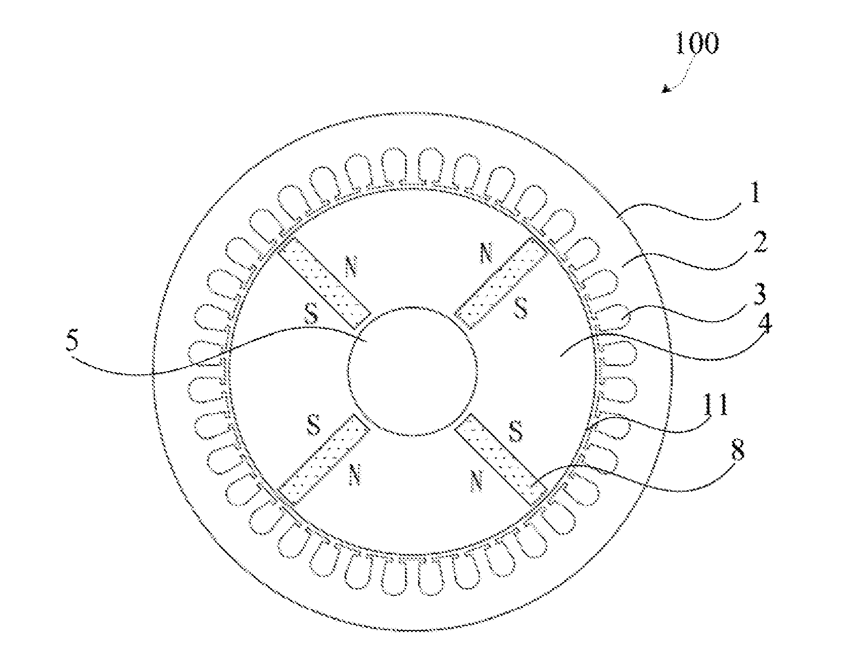
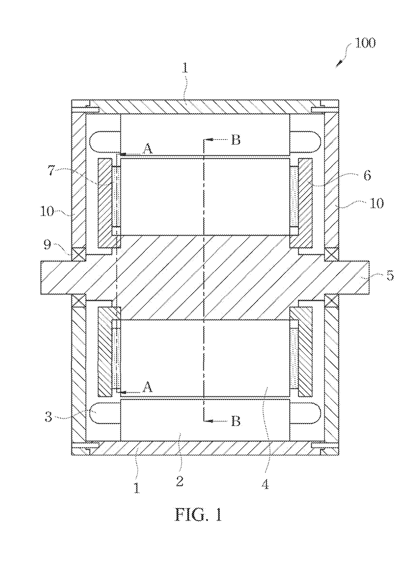
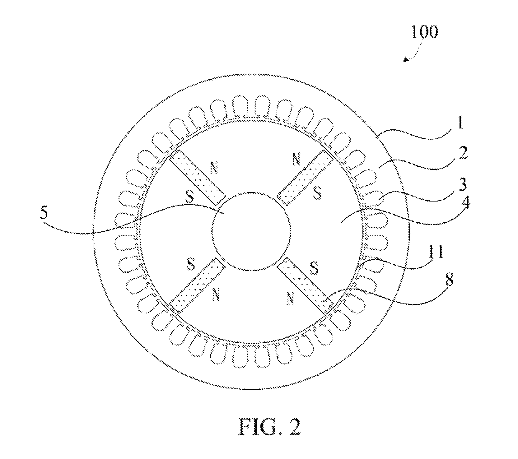
[0040]Referring to FIG. 1, FIG. 1 is a cross-sectional view of an electric machine in an embodiment of the invention. As shown in FIG. 1, a rotary electric machine 100 includes a shell 1, a stator core 2, stator windings 3, a rotor core 4, a shaft 5, a rotor bushing 6, an axial magnetic steel 7, a tangential magnetic steel 8 (as shown in FIG. 2), a shaft bearing 9 and an end cover 10. An electric machine stator is formed from the stator core 2 and the stator windings 3....


PUM


Abstract

A rotor and a rotary electric machine containing the rotor are provided. The rotor includes a shaft, a rotor core coaxially connected to the shaft, a first axial magnetic steel and a second axial magnetic steel disposed at an end surface of the rotor core, a rotor bushing, and a first magnetic isolation groove. The first axial magnetic steel has a first magnetic pole facing the rotor core. The second axial magnetic steel has a second magnetic pole facing the rotor core. The rotor bushing is disposed at a side of the first and second axial magnetic steels opposite to the rotor core. The first magnetic isolation groove is formed in the rotor core along a radius direction of the rotor core. The first magnetic isolation groove is disposed between the first axial magnetic steel and the second axial magnetic steel to isolate the first pole and the second pole.

Description

RELATED APPLICATIONS[0001]The present application is a continuation-in-part application of U.S. application Ser. No. 13 / 306,749, filed Nov. 29, 2011, which itself claims priorities to Chinese Patent Application Serial Number 201110240463.1, filed Aug. 19, 2011. The present application also claims priority under 35 U.S.C. §119(a) on Chinese Patent Application Serial Number 201210287326.8 filed Aug. 13, 2012. The entire contents of the above identified applications are hereby incorporated by reference.BACKGROUND[0002]1. Field of Invention[0003]The invention relates to a rotary electric machine. More particularly, the invention relates to a rotary electric machine with a structure design of permanent magnet (PM).[0004]2. Description of Related Art[0005]A preferred material for forming a PM of an electric machine is neodymium iron boron. However, currently, the price of rare earth materials is rising; and therefore in order to reduce the cost, it is expected in this industry to use perm...

Claims


Application Information

Patent Timeline
Patent Type & Authority Applications(United States)
IPC IPC(8): H02K1/27
CPCH02K1/2713H02K1/2773H02K1/2766H02K1/2706
Inventor ZHU, HONG-LIUYING, JIAN-PINGZHANG, SHI-XIANG
Owner DELTA ELECTRONICS SHANGHAI CO LTD
Why Eureka
Try Eureka