Honeycomb construction for abradable angel wing

a technology of honeycomb and abradable wings, which is applied in the direction of electrical-based machining electrodes, machines/engines, manufacturing tools, etc., can solve the problems of angel wings striking, deterioration of the performance of gas turbines, and increased cooling air, so as to improve abradability and improve sealing. , the effect of less risk of honeycomb failur

Inactive Publication Date: 2013-06-06
GENERAL ELECTRIC CO
View PDF8 Cites 10 Cited by
  • Summary
  • Abstract
  • Description
  • Claims
  • Application Information

AI Technical Summary

Benefits of technology

[0010]The present invention uses sinker electrical discharge machining (“EDM”) to plunge / burn a honeycomb directly into a turbine nozzle sealing flange so it becomes an integral part of the nozzle sealing flange so that when a turbine bucket angel wing in the turbine's sealing assembly rubs the nozzle sealing flange, there is improved sealing between the nozzle sealing flange and the bucket angel wing with less risk of honeycomb failure. Optionally, the honeycomb resulting from the electrode with the sinker electrical discharge machining device being plunged into the block of material can be coated with a coating suitable for corrosion resistance and / or improved abradability. In addition, the block of material in which the honeycomb is formed can be either an integral part of the turbine nozzle or separate from the turbine nozzle. In the latter case, the block of material is welded or brazed to the turbine nozzle after the honeycomb has been formed in such block.

Problems solved by technology

However, the sealing performance of these seal assemblies is not always good, such that more than a desired amount of the cooling air tends to leak into the high temperature combustion gas passage so that the amount of cooling air is increased, causing deterioration in the performance of the gas turbine.
If the clearance is too small, the angel wings will strike the adjacent sealing structures during certain turbine operating conditions.
If the clearance is too large, excessive valuable cooling air will leak from the rotor wheelspace into the hot gas path, decreasing the turbine's efficiency.
While an abradable honeycomb has the ability to significantly reduce the leakage of cooling air into the high temperature combustion gas passage, the secure attachment of traditionally made abradable honeycomb pieces at a bucket / nozzle interface is difficult to ensure.
However, attaching a honeycomb piece reliably to an angel wing is difficult, since brazing thin pieces of metal ribbon means a very small attachment region.

Method used


Image

  • Honeycomb construction for abradable angel wing
  • Honeycomb construction for abradable angel wing
  • Honeycomb construction for abradable angel wing

Examples


Embodiment Construction

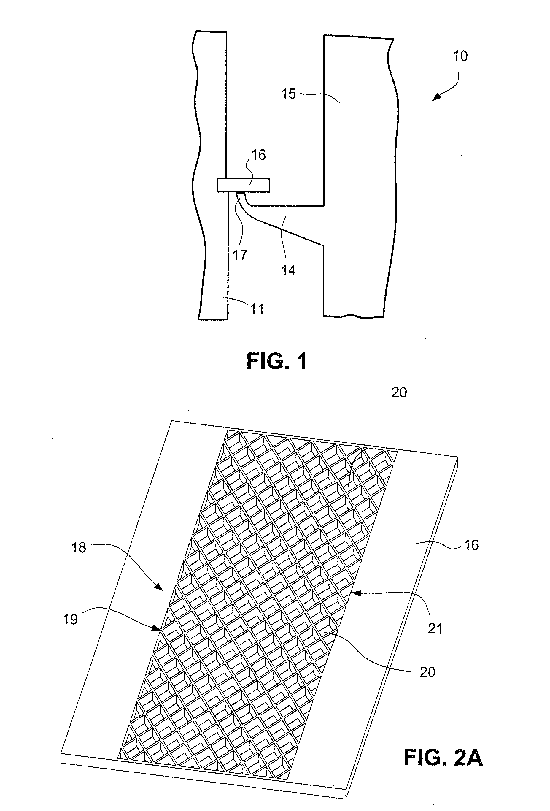
[0021]FIG. 1 is a simple cross-sectional view showing a part of a seal assembly 10 for limiting cooling air from leaking from between a moving bucket 15 and a stationary nozzle 11 of a gas turbine (not shown) into the high temperature combustion gas passage of the turbine. The turbine has a rotor (not shown) rotating about a center longitudinal axis and a plurality of buckets 15 mounted on the outer surface of the rotor. The buckets are spaced from one another circumferentially around the rotor. The buckets 15 also extend radially outward from the rotor. A stationary outer casing (not shown) surrounding and spaced radially outwardly from the buckets defines the high temperature gas passage through the turbine.

[0022]Seal plates, typically referred to as “angel wings”14, extend axially from the upstream and downstream surfaces of the shank portions of the rotating buckets 15. Each of the angel wings 14 ends in a radially outwardly extending tip or cutter tooth 17. Sealing structures o...


PUM

PropertyMeasurementUnit
wall thicknessaaaaaaaaaa
depthaaaaaaaaaa
depthaaaaaaaaaa

Abstract

An abradable honeycomb is integrally formed in a turbine nozzle sealing flange for engagement with a bucket angel wing to reduce the leakage of air into the turbine's hot gas path. The honeycomb is integrally formed in a turbine nozzle sealing flange using a sinker EDM method to directly sink the honeycomb into the sealing flange itself, so that the honeycomb is an integral part of the flange. For repair, an entirely new honeycomb flange can be made and welded or brazed on to the turbine nozzle.

Description

[0001]The present invention relates to turbines, and more particularly, to a method of fabricating an abradable honeycomb as an integral part of a nozzle sealing flange which is engaged by an angel wing of a rotating bucket in a gas turbine to limit cooling air from leaking into the gas turbine's high temperature combustion gas passage.[0002]This invention was made with Government support under contract number DE-FC26-05NT42643 awarded by the Department Of Energy. The Government has certain rights in this invention.BACKGROUND OF THE INVENTION[0003]A gas turbine is a rotary engine that extracts energy from the flow of combustion gas through the turbine. It has an upstream air intake or inlet, a compressor coupled to a combustor, a downstream turbine that receives combustion gas from the combustor, and a gas outlet or exhaust nozzle.[0004]The compressor and turbine sections include at least one circumferential row of rotating rotor blades or buckets. The free ends or tips of the bucke...

Claims


Application Information

Patent Timeline
Patent Type & Authority Applications(United States)
IPC IPC(8): B23H1/00B23H9/00B23P15/00
CPCF05D2250/283F05D2230/12B23H2200/30Y10T29/49982B23H9/10F01D11/001Y10T29/49297B23H1/04
Inventor LACY, BENJAMIN PAULCHUPP, RAYMONDSHENG, NUO
Owner GENERAL ELECTRIC CO
Why Eureka
Try Eureka