Roller-based imprinting system

a technology of imprinting system and roller, which is applied in the direction of printing, photomechanical treatment, instruments, etc., can solve the problems of difficult to overcome extreme small curvature in structural pattern formation on a plane, and achieve the effect of smooth imprinting of pattern layer on the substra

Inactive Publication Date: 2013-06-06
CHUNG YUAN CHRISTIAN UNIVERSITY
View PDF5 Cites 7 Cited by
  • Summary
  • Abstract
  • Description
  • Claims
  • Application Information

AI Technical Summary

Benefits of technology

[0008]In another embodiment, the rotation speed is adapted to match with a moving speed of the movable stage for imprinting the pattern layer onto the substrate smoothly.

Problems solved by technology

However, in view of the optical aspect, since there is a physical limitation on focusing depth, even forming structural patterns on a plane with an extreme small curvature is still difficult to overcome, as well as the bottle neck of linewidth reduction.

Method used


Image

  • Roller-based imprinting system
  • Roller-based imprinting system
  • Roller-based imprinting system

Examples


Embodiment Construction

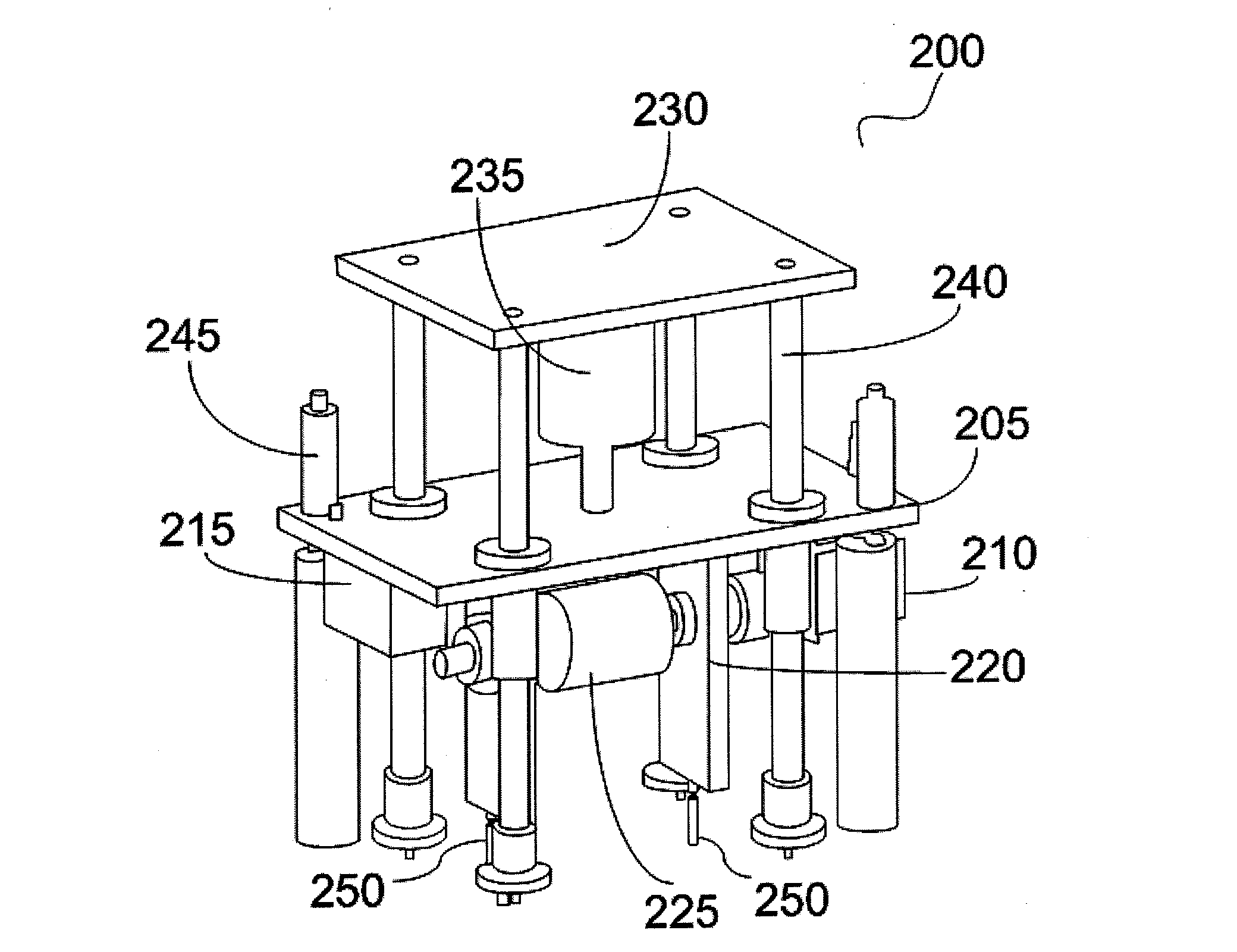
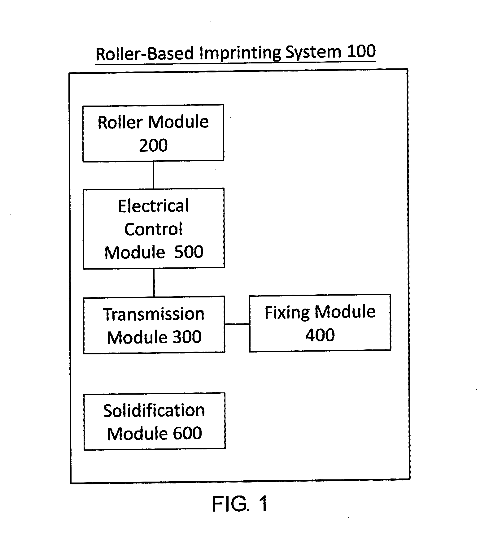
[0033]Refer to FIG. 1, which is a system block diagram of a roller-based imprinting system according to an embodiment. Roller-based imprinting system 100 mainly includes a roller module 200, a transmission module 300, a fixing module 400, an electrical control module 500, and a solidification module 600. The transmission module 300 is electrically connected with the fixing module 400 and the electrical control module 500. (or physically connected through a linking mechanism), thereby driving the fixing module 400 to move within the roller-based imprinting system 100, and controlling the position of the fixing module 400 by the electrical control module 500. A substrate for imprinting process is positioned on the fixing module 400. The roller module 200 is electrically connected with the electrical control module 500, such that the electrical control module 500 is able to adjust the positions of a roller of the roller module 200 to vertically press the substrate fixed on the fixing m...


PUM


Abstract

A roller-based imprinting system includes a roller module, a transmission module, a fixing module, a solidification module, and a controlling module. The roller-based imprinting system imprints and transfers a pattern located on the surface of a soft mold to the substrate through the pressing force of the roller.

Description

CROSS-REFERENCES TO RELATED APPLICATIONS[0001]This non-provisional application claims priority under 35 U.S.C. § 119(a) on Patent Application No. 100144906 filed in Taiwan, R.O.C. on Dec. 6, 2011, the entire contents of which are hereby incorporated by reference.BACKGROUND[0002]1. Technical Field[0003]The disclosure relates to an imprinting device, and in particular to a roller-based imprinting system adapted to transfer a pattern of a soft mold onto a substrate.[0004]2. Related Art[0005]Nowadays, “minimal”, “light”, “thin”, “compact” with high performance are the main characteristics emphasized for electronic products; that also means the core components produced by semiconductor manufacturers have to be continuously developed in exactly the same directions. Currently the major bottle neck of technology development in semiconductor industry is linewidth size. When linewidth size becomes shorter, the size of a core component is able to be reduced as well. Regarding to performance, s...

Claims


Application Information

Patent Timeline
Patent Type & Authority Applications(United States)
IPC IPC(8): B41F3/02
CPCG03F7/0002B82Y40/00B82Y10/00
Inventor LEE, YEEU-CHANGWU, TSO-HSIANGCHEN, BO-TING
Owner CHUNG YUAN CHRISTIAN UNIVERSITY
Why Eureka
Try Eureka