Plasma tube array-type display device

Inactive Publication Date: 2013-06-06
SHINODA PLASMA
View PDF6 Cites 5 Cited by
  • Summary
  • Abstract
  • Description
  • Claims
  • Application Information

AI Technical Summary

Benefits of technology

[0015]As described above, the plasma tubes each has a transverse section orthogonal to the longitudinal direction of a vertically long, flattened shape having its longer diameter vertically, and they form a plasma tube array in which they are arranged to adjoin each other by their tube walls of longer diameter side. This makes it possible to reduce the size in width of the plasma tubes in

Problems solved by technology

However, in the case of the configuration of the plasma tube disclosed in JP 2003-068214 A (U.S. Pat. No. 6,677,704B), it is very difficult to make the high-resolution display with a pixel size of 3 mm or less, because the shorter diameter in a vertical direction becomes extremely shor

Method used


Image

  • Plasma tube array-type display device
  • Plasma tube array-type display device
  • Plasma tube array-type display device

Examples


embodiment 1

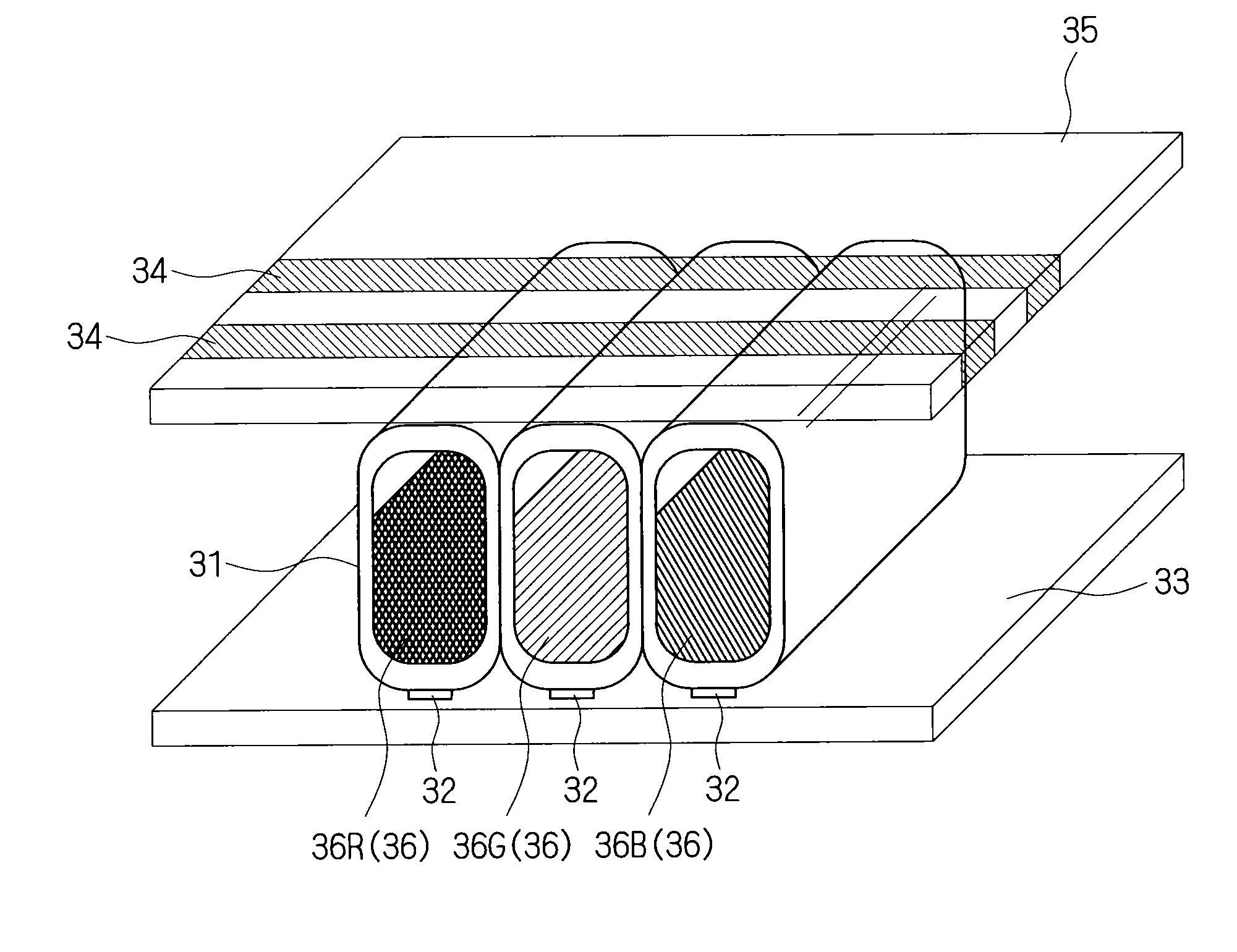
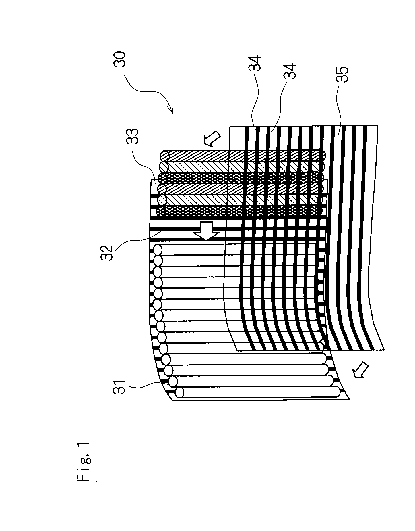
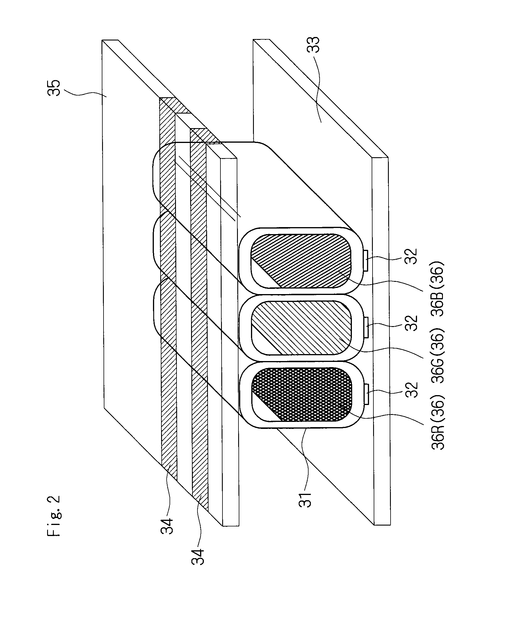
[0024]FIG. 1 is a perspective view schematically showing the configuration of a plasma tube array-type display device according to Embodiment 1 of the present invention. As shown in FIG. 1, the plasma tube array-type display device 30 according to Embodiment 1 includes a plurality of plasma tubes 31, 31, . . . arranged in parallel, each of which is filled with a discharge gas. The plasma tubes 31, 31, . . . are shown to have circular sections for convenience sake but are actually gas discharging thin tubes (plasma tube) made of glass having a vertically long, flattened cross section as described later in detail. The diameter of each glass thin tube to serve as a tube envelope is not particularly limited. Desirably, however, the shorter diameter is 1 mm or less and the longer diameter is approximately 1 to 3 mm. Furthermore, the plasma tubes 31, 31, . . . are filled with a discharge gas mixture such as neon, xenon and the like at a predetermined ratio and a predetermined pressure.

[00...

embodiment 2

[0045]Since the configuration of a plasma tube array-type display device 30 according to Embodiment 2 of the present invention is similar to that of Embodiment 1, the same numbers and symbols are used and detailed descriptions are not repeated. In Embodiment 2, the plasma tubes 31 each are different from those of Embodiment 1 in that the width of the first flat surface (lower flat surface) 41 that is in contact with the address electrode 32 is narrower than that of the second flat surface (upper flat surface) 42 that is in contact with the display electrode 34.

[0046]FIG. 6 is a cross-sectional view taken at a plane orthogonal to the longitudinal direction of the plasma tubes 31, 31, . . . of the plasma tube array-type display device 30 according to Embodiment 2 of the present invention. As shown in FIG. 6, each plasma tube 31 of the plasma tube array-type display device 30 according to Embodiment 2 also has a transverse section orthogonal to the longitudinal direction of a verticall...

embodiment 3

[0055]In Embodiment 3, the plasma tubes 31 each have a transverse section orthogonal to the longitudinal direction of a substantially vertically long, flattened, trapezoidal shape and are different from those of Embodiment 1 in the array form in which they are combined together with the upper and lower sides thereof being inverted.

[0056]FIG. 8 is a cross-sectional view schematically showing the configuration of a plasma tube unit of a plasma tube array-type display device 30 according to Embodiment 3 of the present invention. In FIG. 8, each plasma tube 31 comprises a red (R) phosphor layer 36R, a blue (B) phosphor layer 36B, or a green (G) phosphor layer 36G on the narrower top side inner surface or a wider bottom side inner surface of the vertically long, flattened, trapezoidal cross section. When a plasma tube unit corresponding to one pixel composed of one set of plasma tubes 31, 31, and 31 of three colors RGB is configured, the plasma tube array-type display device is capable o...


PUM


Abstract

A plasma tube array-type display device has an improved high resolution and sufficient brightness. In the plasma tube array-type display device comprising a plasma tube array that includes a plurality of plasma tubes 31, 31, . . . arranged in parallel, each plasma tube 31 has a transverse section orthogonal to the longitudinal direction of a vertically long, flattened shape having its longer diameter vertically, and the plurality of plasma tubes 31, 31, . . . are arranged to adjoin each other by their tube walls of longer diameter side.

Description

BACKGROUND OF THE INVENTION[0001]1. Field of the Invention[0002]The present invention relates to a plasma tube array-type display device including a plurality of plasma tubes arranged in parallel. Particularly, the present invention relates to a plasma tube array-type display device having an improved high resolution (high density) and sufficient brightness.[0003]2. Description of the Related Art[0004]Plasma tube array-type display devices have been developed as a technology for providing new-generation large-screen display devices. They each include a plurality of plasma tubes filled with a discharge gas that are arranged in parallel. For example, the plasma tube array-type display device is constructed as a film display device in which 1000 plasma tubes or more with a length of 1 to 2 meters are arranged in parallel. Furthermore, for example, the plasma tube array-type display device of one meter square is used as a sub-module, a plurality of sub-modules are connected to one anoth...

Claims


Application Information

Patent Timeline
IPC IPC(8): H01J17/49
CPCH01J17/49H01J11/18
Inventor MORITA, YOSHIROHIRAKAWA, HITOSHIGUO, BINGANGTANAKA, HAJIMEDAN, NORIHISA
Owner SHINODA PLASMA
Why Eureka
Try Eureka