Magnetic Inductive Type Position Sensor

a position sensor and magnetic induction technology, applied in the direction of electrical/magnetic position measurement, converting sensor output electrically/magnetically, instruments, etc., can solve the problem of uneven magnetic induction characteristic, increase the overall fabrication cost of the sensor, and increase the error of the output signal, so as to reduce the deformation of each wing member and achieve uniform sensor measurement value.

Active Publication Date: 2013-06-06
LG INNOTEK CO LTD
View PDF3 Cites 2 Cited by
  • Summary
  • Abstract
  • Description
  • Claims
  • Application Information

AI Technical Summary

Benefits of technology

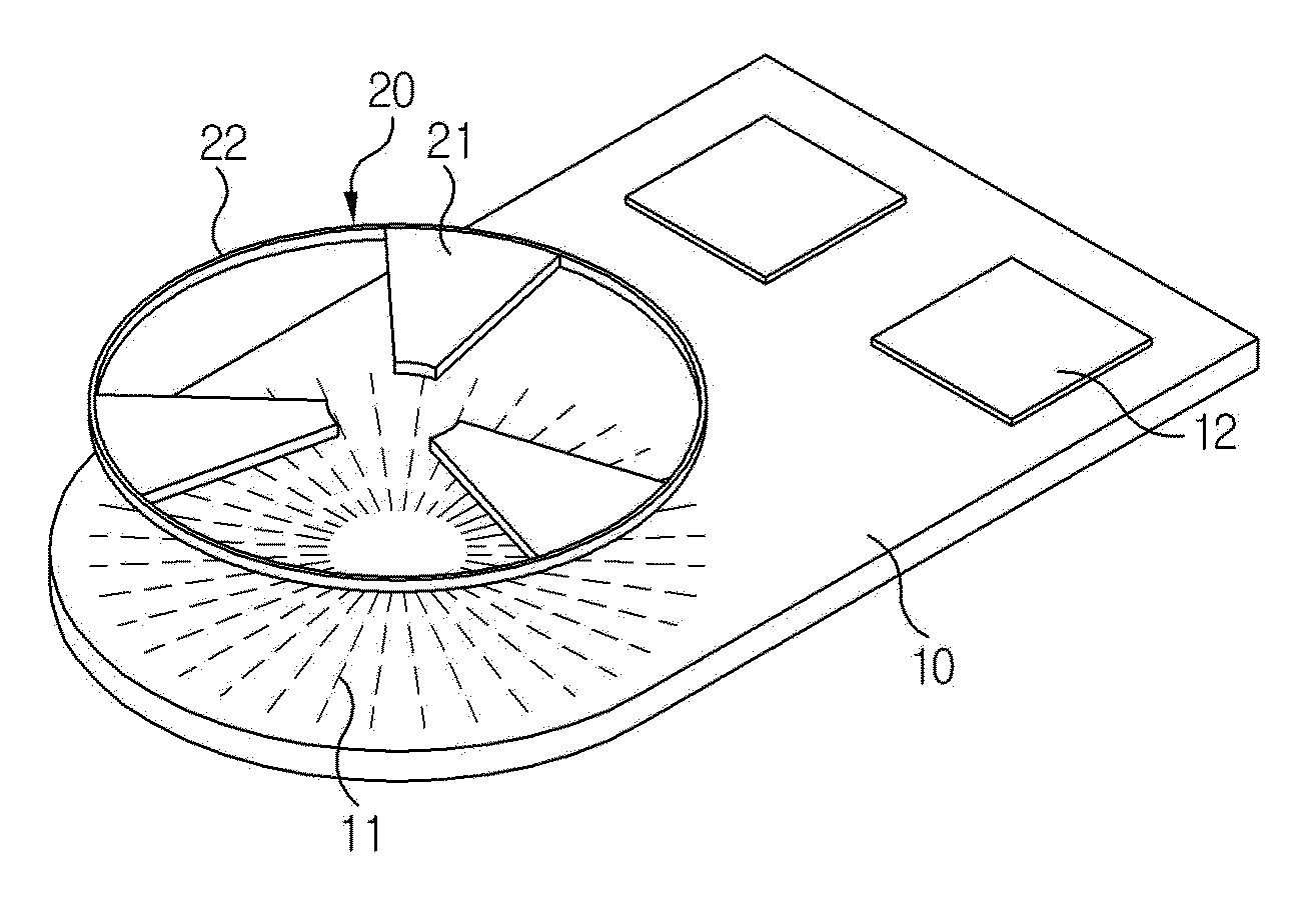
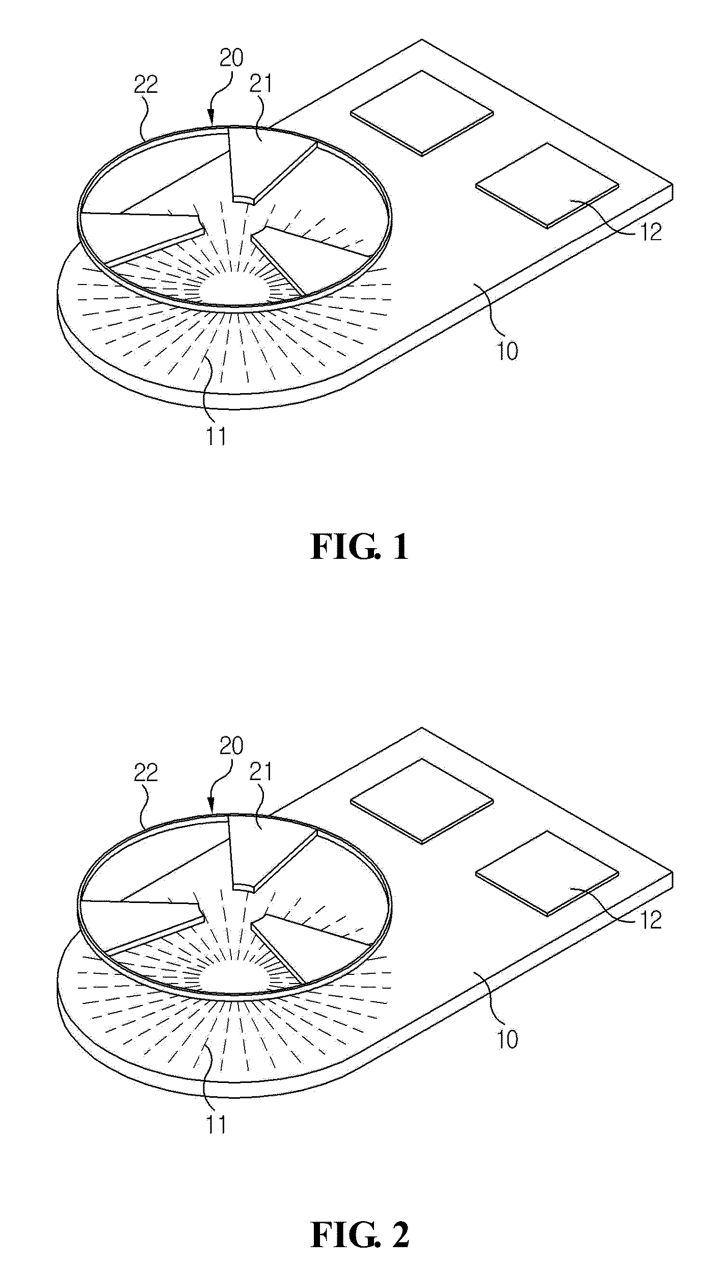
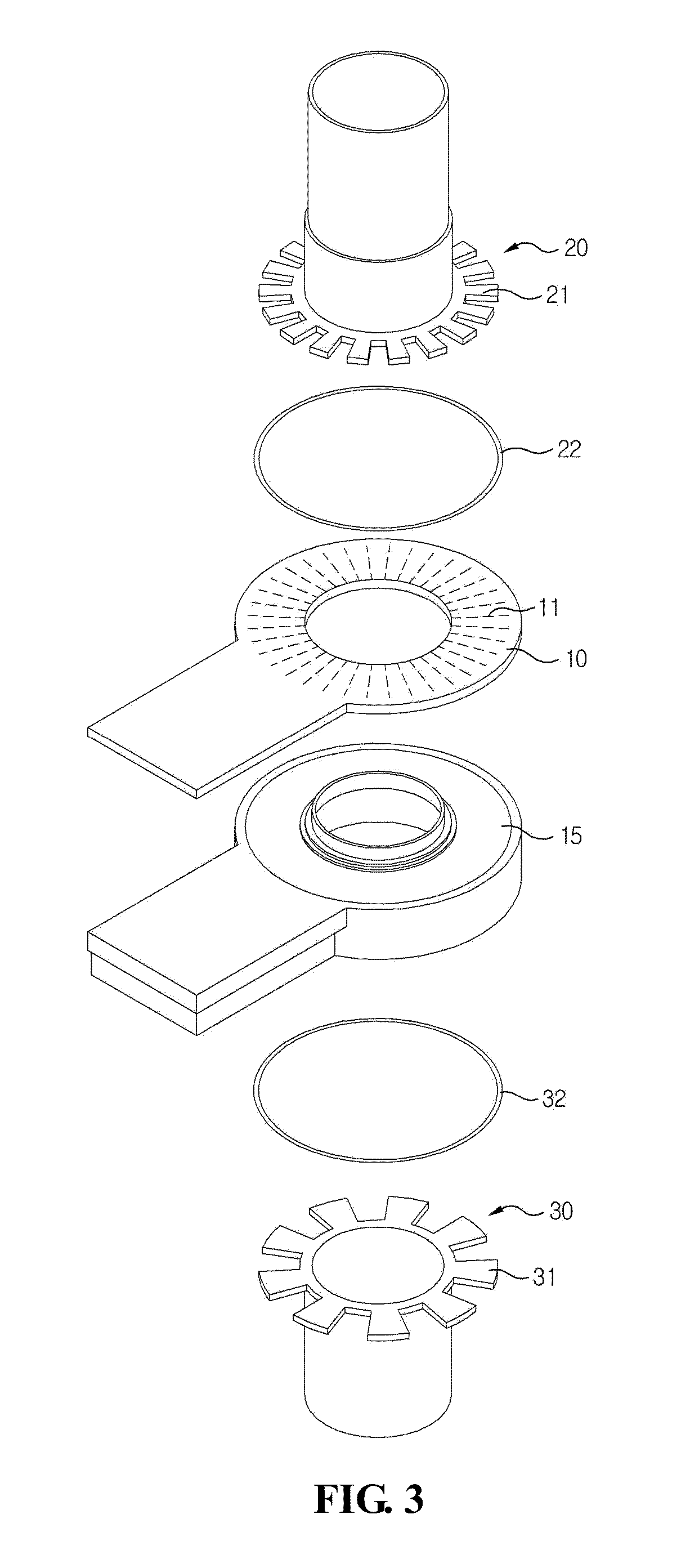
[0024]The magnetic inductive type position sensor thus configured according to the present disclosure has an advantageous effect in that distal ends of wing members are mutually connected in the course of manufacturing the wing members of a rotor to minimize deformation of each wing member, whereby flatness of wing members can be constantly configured to thereby maintain a uniform sensor measurement value.

Problems solved by technology

However, the conventional methods are disadvantageous in that, in a case flatness of geometries protrusively and radially formed on the disk is not uniform, a gap between the PCB and the geometries may not be constantly maintained to generate an uneven magnetic induction characteristic.
This mechanical problem disadvantageously results in a ripple phenomenon in an output characteristic of a detection sensor to increase an overall fabrication cost of the sensor and an error of the output signal.

Method used


Image

  • Magnetic Inductive Type Position Sensor
  • Magnetic Inductive Type Position Sensor
  • Magnetic Inductive Type Position Sensor

Examples


Embodiment Construction

[0032]Advantages and features of the present disclosure may be understood more readily by reference to the following detailed description of exemplary embodiments and the accompanying drawings. Detailed descriptions of well-known functions, configurations or constructions are omitted for brevity and clarity so as not to obscure the description of the present disclosure with unnecessary detail. Thus, the present disclosure is not limited to the exemplary embodiments which will be described below, but may be implemented in other forms. In the drawings, the width, length, thickness, etc. of components may be exaggerated or reduced for the sake of convenience. Furthermore, throughout the descriptions, the same reference numerals will be assigned to the same elements in the explanations of the figures, and explanations that duplicate one another will be omitted. Accordingly, the meaning of specific terms or words used in the specification and claims should not be limited to the literal o...


PUM


Abstract

Disclosed is a magnetic inductive type position sensor, the position sensor including at least one rotor body coupled to a rotation shaft to rotate in association with rotation of the rotation shaft and having a plurality of protrusively and circumferentially formed wing members, a PCB arranged in opposition to the rotor body, and a guide member connecting each distal end of the wing members to guide each of the wing members to be aligned on the same planar surface.

Description

CROSS-REFERENCE TO RELATED APPLICATION[0001]This application claims the benefit under 35 U.S.C. §119 of Korean Patent Application No. 10-2011-0127511, filed Dec. 1, 2011, which is incorporated by reference herein in its entirety.BACKGROUND[0002]1. Field of the Invention[0003]The present disclosure relates to a position sensor using a magnetic induction.[0004]2. Discussion of the Related Art[0005]This section provides background information related to the present disclosure which is not necessarily prior art.[0006]Various forms of sensors have been used to measure a position of a rotation shaft in response to interactive movement between a rotor and a stator. Among the various methods, an example of a position sensor using a magnetic induction is disclosed by European Registered Patent No.: EP 1081454 and a U.S. Registered Pat. No.: 6,384, 598.[0007]In the above mentioned prior art, a rotor is disposed with a disk, and the disk is formed with a plurality of fan-like geometries. A PCB...

Claims


Application Information

Patent Timeline
Patent Type & Authority Applications(United States)
IPC IPC(8): G01B7/30
CPCG01D5/145G01B7/30G01D5/20G01B7/003G01D5/2033
Inventor LEE, CHANGHWAN
Owner LG INNOTEK CO LTD
Why Eureka
Try Eureka