Head up display (HUD)

a display and head-up display technology, applied in the field of optical systems, can solve the problems of not being able to reduce the size of the optical elements used for the head-up display further, and it is not easy to integrate such a single optical element, and achieve the effect of large display area, safety and efficiency, and high-quality head-up display

Active Publication Date: 2013-06-06
AUTOMOTIVE RES & TESTING CENT
View PDF10 Cites 21 Cited by
  • Summary
  • Abstract
  • Description
  • Claims
  • Application Information

AI Technical Summary

Benefits of technology

[0007]In view of the problems and shortcomings of the prior art, the present invention provides a Head Up Display (HUD), for which size of optical elements such as l

Problems solved by technology

As such, a Head Up Display requires an enormously large lens or mirror to project out virtual images, thus it is not easy to integrate such a single optical-route display device with an instrument panel into an integral unit, since the volume required by such a Head Up Display would be too large for the panel full of wires and connections.
In addition, in order to keep the quality of imaging, the size of optical elements used for a Head Up Display can not be reduced further, therefore, it is rather difficult to achieve large display area in a very li

Method used


Image

  • Head up display (HUD)
  • Head up display (HUD)
  • Head up display (HUD)

Examples


first embodiment

[0033]Subsequently, refer to FIGS. 4, 5, 6, and 7 respectively for a schematic diagram of image formation of virtual image generation unit, large area image formation, optical characteristics of a concave lens, and a curved mirror image formation according to the present invention. As shown in FIGS. 4 and 5, the virtual image generation unit 22 can be a concave lens 38 or a convex lens 40, either of them utilizes optical principle of upright magnified virtual image to generate virtual images, thus image is formed outside the window in a large area manner, such that the virtual image generated can at least match the actual lane marking 42, and corresponds to the virtual image lane marking 44.

[0034]As shown in FIG. 6, the optical characteristics of the concave lens 38 of the present invention are that, when its radius of curvature R is ∞, then it is a concave lens 38, with its focal length cc; and when its radius of curvature R is 100, then it is an arc concave lens 38, with its focal...

second embodiment

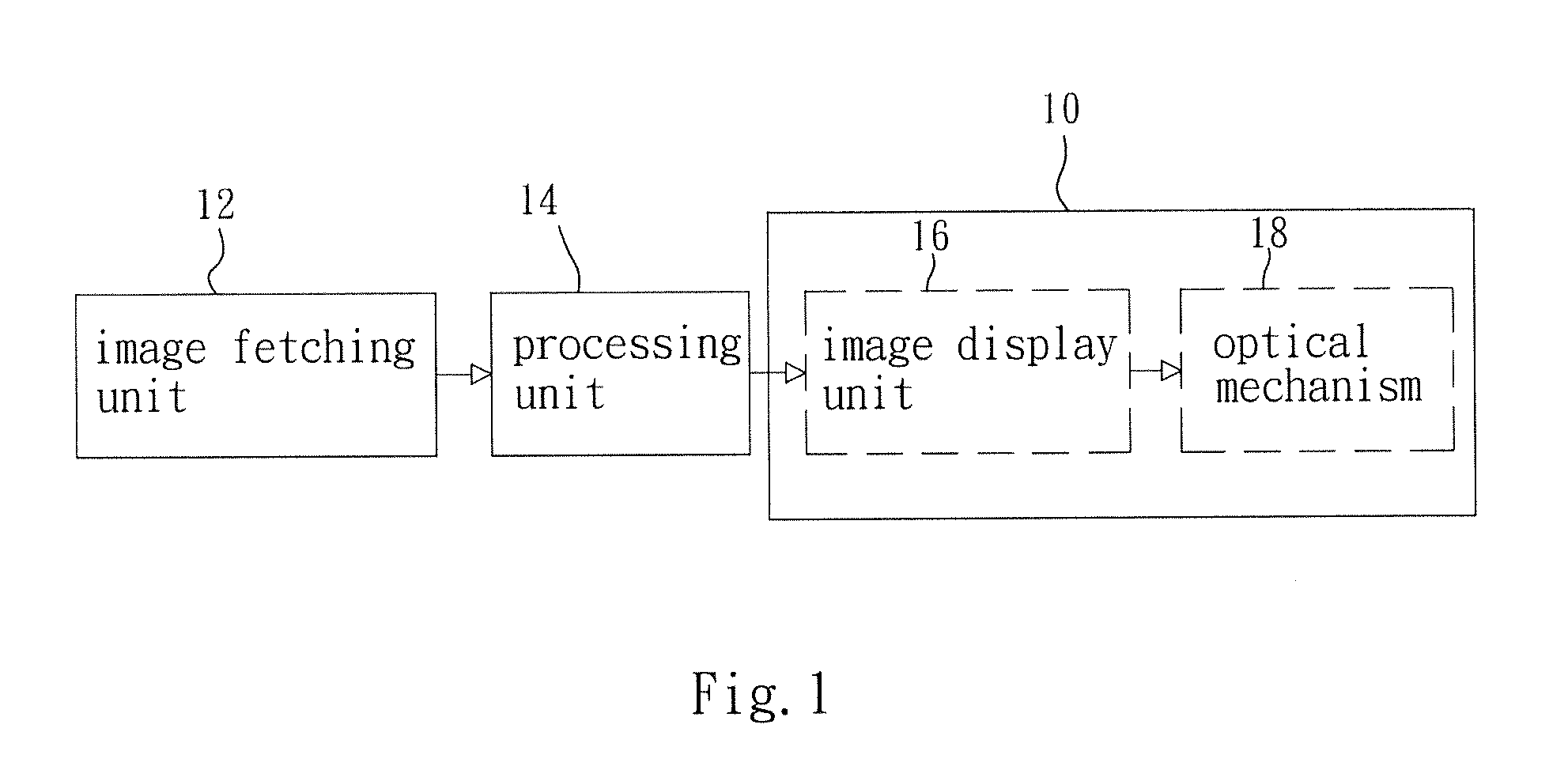
[0039]Finally, refer to FIG. 10 for a system block diagram of a Head Up Display (HUD) according to the present invention, meanwhile refer to FIGS. 4, 9A, 9B, and 9C. As shown in FIG. 10, a head up display (HUD) 10 further includes a light source generation element 65, that can serve as a light source. In the optical mechanism 18, a digital micro-mirror device (DMD) is used to realize the image display unit 66. Since the image display unit 66 is composed of a plurality of micro-mirrors to form into a matrix array, and each input image contains a plurality of pixels, so each of micro-mirrors corresponds to each of the pixels, such that the number of micro-mirrors on the image display unit 66 is equal to the number of pixels.

[0040]When the image display unit 66 receives lights coming from the light source generation element 65, it generates one or more input images. Since the image display unit 66 is able to control the on and off states of each pixel (similar to a digital switch 1-on ...


PUM


Abstract

A Head Up Display (HUD), comprising: an image display unit, to generate input images; a virtual image generation unit, to receive said input images and generate at least a virtual image; a rotation mechanism, used to make said virtual image generation unit to change its projection angle, to project virtual images to a plurality of transmission mirrors; and a plurality of transmission mirrors, used to receive said virtual images and reflect them into a large area virtual image. Advantage of said HUD is that, size of lens and mirrors is reduced, so said HUD is miniaturized, while realizing large area image display, such that information frame of vehicle match that of outside view, hereby solving problems of single optical route display device of the prior art, that is only capable of displaying a small area image rather than a large area image.

Description

BACKGROUND OF THE INVENTION[0001]1. Field of the Invention[0002]The present invention relates to an optical system, and in particular to a Head Up Display (HUD) suitable for use in a moving vehicle.[0003]2. The Prior Arts[0004]It is well known that the Head Up Display (HUD) is an auxiliary aviation instrument that is first utilized in an aircraft, so that a pilot is able to look at the information on the panel without lowering his head, to avoid interruption of attention and lose Situation Awareness. The Head Up Display (HUD) can not only provide convenience in usage, but it can also raise the aviation safety. Therefore, it can be used in any types of the moving vehicles, such as aircrafts, or even automobiles and ships.[0005]In the past, the Head Up Display of the prior art could provide only a small display area of simple instrument information within the eyesight of the driver, to indicate the critical information related to the moving vehicle. For the Head Up Displays (HUD) of t...

Claims


Application Information

Patent Timeline
IPC IPC(8): G09G5/00G02B26/00G02B27/01
CPCG09G3/003G09G2340/12G09G2340/14G02B27/0101G09G2380/10G02B26/0833G09G2354/00
Inventor HO, KEVINHSU, JIH-TAOCHIANG, CHIH-BIN
Owner AUTOMOTIVE RES & TESTING CENT
Why Eureka
Try Eureka