Router, method for controlling router, and program

a router and router technology, applied in the field of routers, can solve the problems of increasing the difficulty of designing an integrated circuit by such a centralized bus control, increasing the difficulty of routing traffic through the transmission path, and increasing the scale of the circuit, so as to reduce the delay of data transfer

Active Publication Date: 2013-06-06
PANASONIC INTELLECTUAL PROPERTY MANAGEMENT CO LTD
View PDF6 Cites 47 Cited by
  • Summary
  • Abstract
  • Description
  • Claims
  • Application Information

AI Technical Summary

Benefits of technology

[0017]According to the above aspect, a transfer delay of a traffic of data

Problems solved by technology

However, as the functionality of an integrated circuit has been improved and as the number of cores in an integrated circuit has been increased, the scale of the circuit has become larger and the traffic flow through the transmission path has gotten more complicated.
As a result, it has become increasingly difficult to design an integrated circuit by such a centralized bus control.
In the router, a transfer process of traffic may be delayed due to, for example, a wait at each buffer or a process delay at the crossbar switch.
As the scale of the network becomes larger, the number of routers is increased, and thus the problem of delay becomes more serious.
For this reason, while a bursty traffic is transferred, a traffic jam is likely to occur to cause a transfer d

Method used


Image

  • Router, method for controlling router, and program
  • Router, method for controlling router, and program
  • Router, method for controlling router, and program

Examples


embodiment 1

1. Overview of this Embodiment

[0121]First, a first embodiment of the present disclosure will be described. This embodiment provides a technology for solving the problem of traffic jam which may occur when a bypass process is executed. First, with reference to FIG. 1A and FIG. 1B, problems caused by the bypass process will be described.

1.1 Problems Caused by Bypass Process

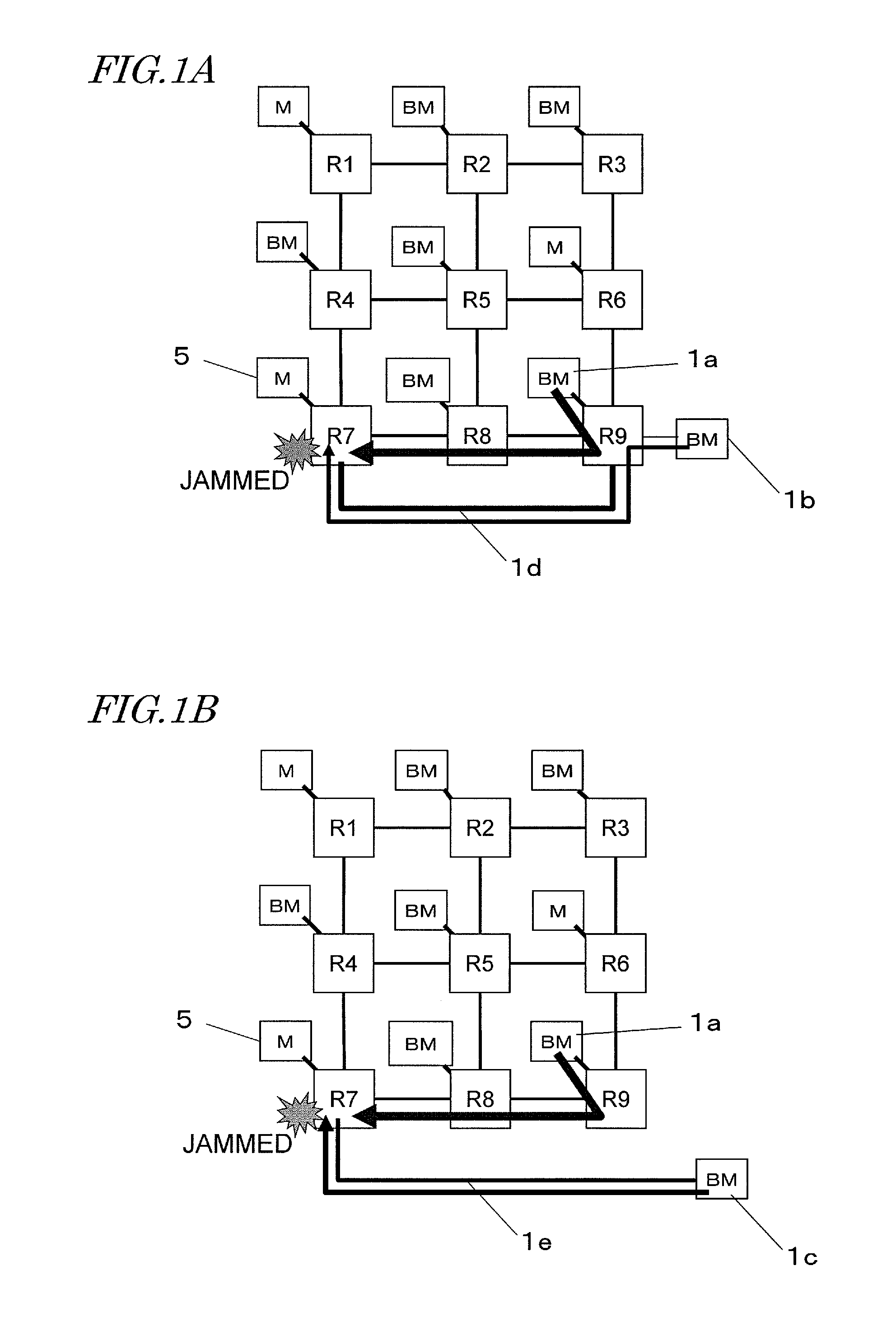
[0122]FIG. 1A shows an example of configuration of a data transfer system for performing transmission and receiving of data between a plurality of bus masters (BM) and a plurality of memories (M) via a plurality of routers R1 through R9. In the example of configuration shown here, the plurality of routers R1 through R9 are connected in a mesh via a bus, and each router is connected to a bus master or a memory. Between the router R9 and the router R7, a bypass path 1d is provided.

[0123]In this example of configuration, from a bus master 1a connected to the router R9, data is transmitted to a memory 5 via the routers ...

embodiment 2

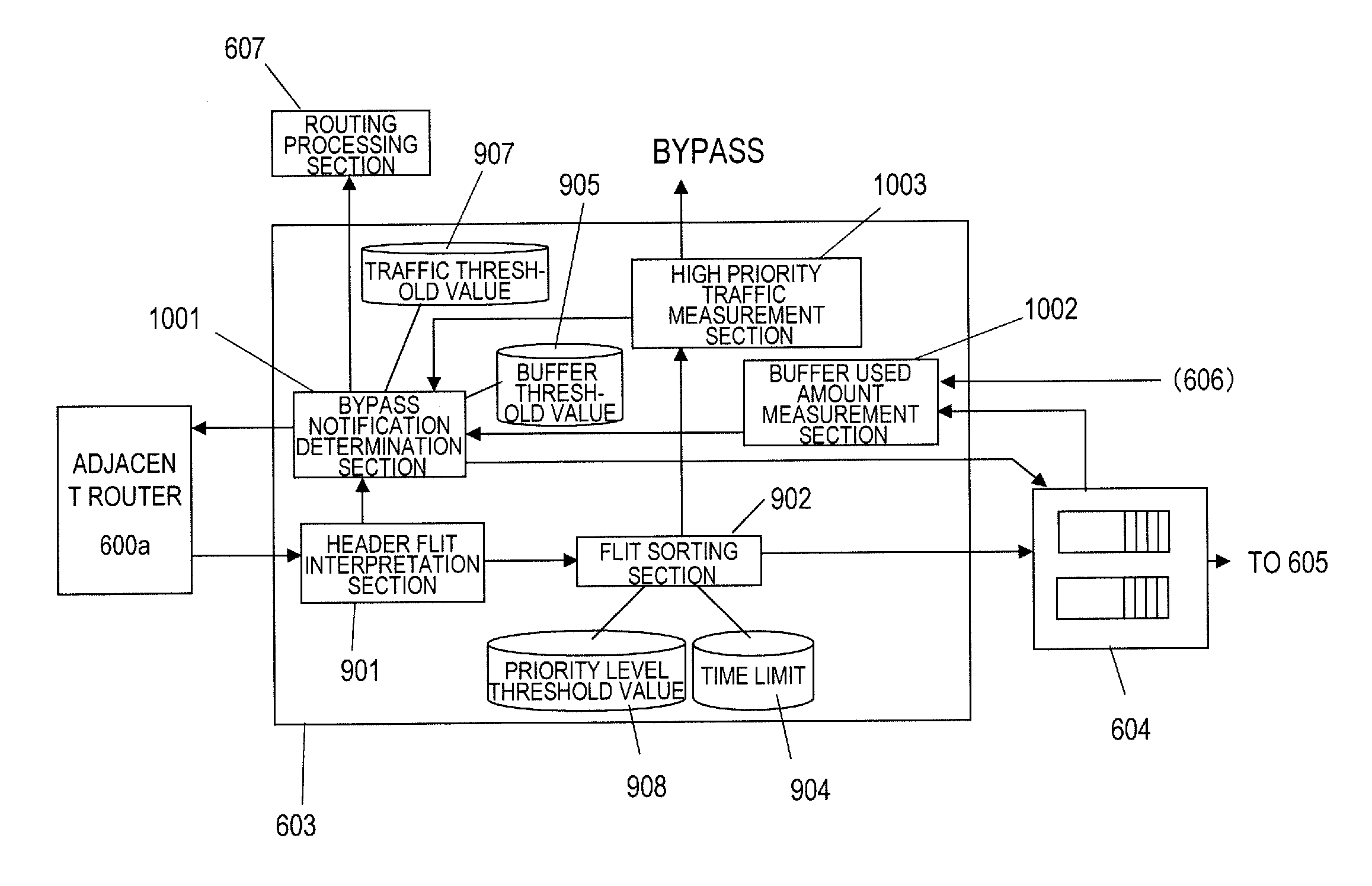
[0276]Now, a router according to a second embodiment of the present disclosure will be described.

[0277]In the first embodiment, the bypass lines are provided in a router or between routers. In this embodiment, the routers are not provided with bypass lines. In the following description, a traffic corresponding to the bypass traffic in the first embodiment will be referred to as a “high priority traffic”, and a traffic corresponding to the non-bypass traffic in the first embodiment will be referred to as a “low priority traffic”. The “high priority traffic” is a traffic required to be transferred with low latency such as, for example, video data or audio data, or a traffic having a high emergency level such as information representing a command issued by the user or notifying system abnormality. The “low priority traffic” is a traffic having a low emergency level such as, for example, data on file transfer or data of an application to be processed in the background. Whether a traffic...

embodiment 3

[0296]Now, a third embodiment according to the present disclosure will be described.

[0297]Before describing this embodiment in detail, the basic principle of this embodiment will be first described.

[0298]FIG. 27 is a block diagram showing a schematic configuration of a router 600 in this embodiment. The router 600 includes an input section 400 for receiving a packet, a bypass control section 200 for determining whether to perform a bypass process of outputting an incoming data transfer unit (packet) with priority or to perform a usual process of not outputting the incoming data transfer unit with priority, and a switch 605 for selecting a transmission path for the packet not to be bypassed from a plurality of paths. In the example shown in FIG. 27, a packet to be bypassed is output through a bypass path 300, and a packet not to be bypassed is output through a non-bypass path 350.

[0299]The bypass path 300 corresponds to, for example, a path passing the bypass line 930 shown in FIG. 5...


PUM


Abstract

A router includes an input section configured to receive data, a buffer section including a plurality of data storage sections and configured to store the data received by the input section, and an output section configured to output the data stored on the buffer section. The router also includes an allocation processing section configured to determine whether or not to store the data on a pre-secured specific data storage section among the plurality of data storage sections, or whether or not to store the data on a pre-secured specific data storage section among a plurality of data storage sections in a buffer section of another router which is an output destination, the determination being made based on information representing burstiness of the data received by the input section.

Description

[0001]This is a continuation of International Application No. PCT / JP2012 / 001625, with an international filing date of Mar. 9, 2012, which claims priority of Japanese Patent Application No. 2011-070637, filed on Mar. 28, 2011, Japanese Patent Application No. 2011-070638, filed on Mar. 28, 2011, Japanese Patent Application No. 2011-070639, filed on Mar. 28, 2011, Japanese Patent Application No. 2011-070640, filed on Mar. 28, 2011, the contents of which are hereby incorporated by reference.BACKGROUND[0002]1. Technical Field[0003]The present disclosure relates to a router in a semiconductor system including a bus, a method for controlling the router, and a program.[0004]2. Description of the Related Art[0005]There are various methods for controlling the transfer in a data transfer system including a bus. FIGS. 53A and 53B each show an exemplary known transfer control method for a conventional semiconductor system. FIG. 53A shows an example of conventional centralized bus control. In the...

Claims


Application Information

Patent Timeline
IPC IPC(8): H04L12/56H04L45/17H04L47/56
CPCH04L45/00H04L49/109H04L47/12H04L49/252H04L49/505H04L47/70
Inventor YAMAGUCHI, TAKAOYOSHIDA, ATSUSHIISHII, TOMOKI
Owner PANASONIC INTELLECTUAL PROPERTY MANAGEMENT CO LTD
Why Eureka
Try Eureka