Fan arrangement

Inactive Publication Date: 2013-06-06
ROBERT BOSCH GMBH
View PDF21 Cites 5 Cited by
  • Summary
  • Abstract
  • Description
  • Claims
  • Application Information

AI Technical Summary

Benefits of technology

[0010]It is the object of the present invention to make available a ventilator fan with which an improved discharge flow of the conveyed air, and thereby improved efficiency, can be ach

Problems solved by technology

In addition, the overall height, which determines the necessary distance between the fan

Method used


Image

  • Fan arrangement
  • Fan arrangement
  • Fan arrangement

Examples


Embodiment Construction

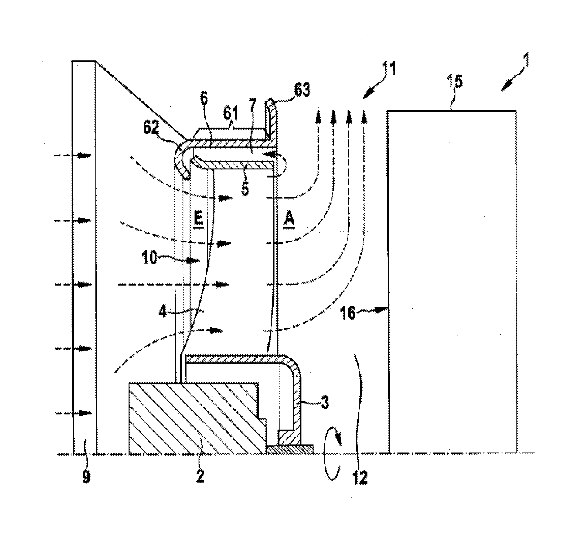
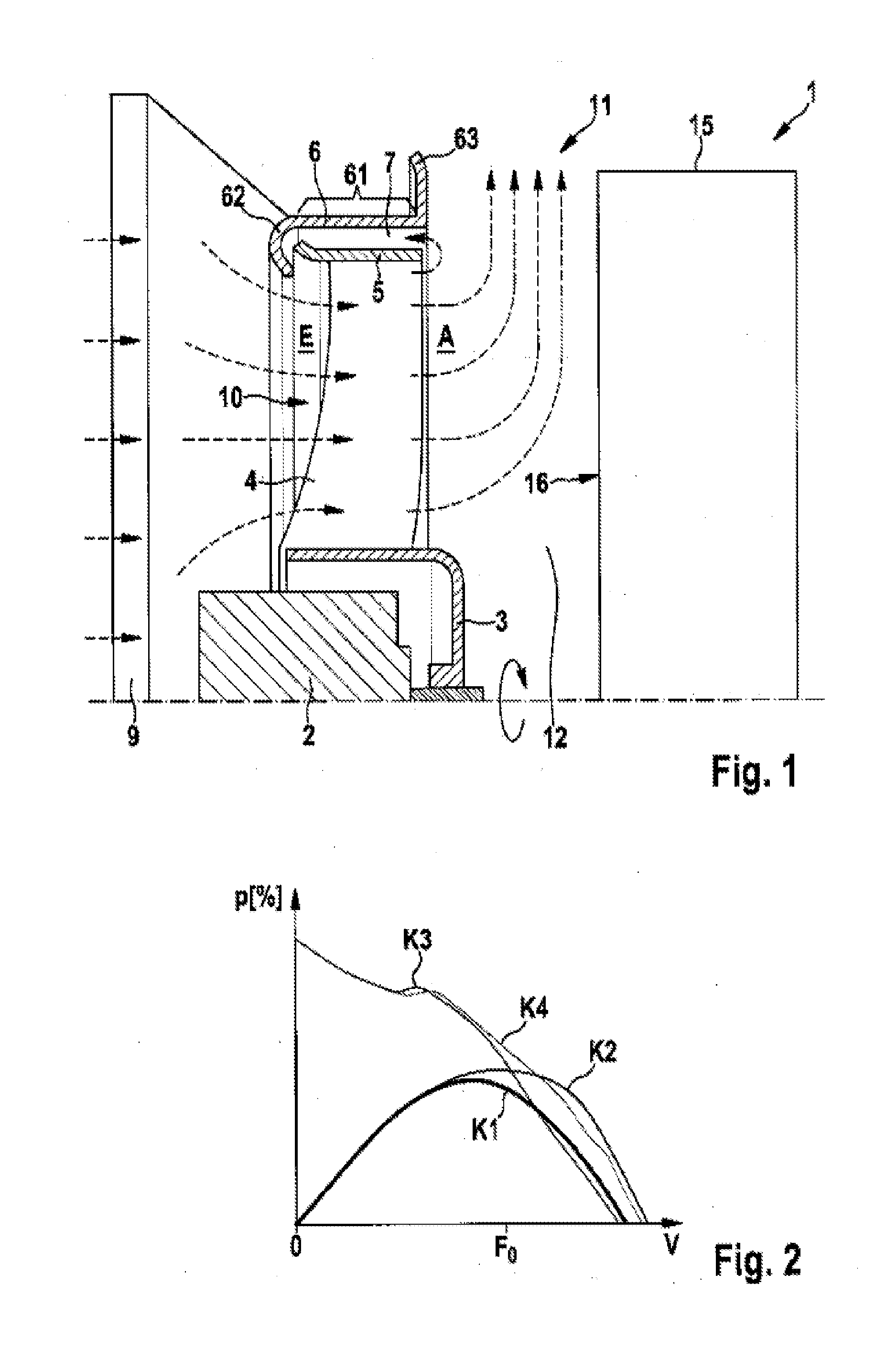
[0029]FIG. 1 shows a cross-sectional view of an embodiment of the fan arrangement 1. The fan arrangement 1 may be used in motor vehicles in order to cool a cooling device 9. The cooling device 9 may be arranged on the inlet side of the fan arrangement 1 and may be used to dissipate to the environment the waste heat produced during operation of an internal combustion engine or other drive unit.

[0030]An outlet side A of the fan arrangement 1 is arranged at a distance from a block 15, such as an internal combustion engine, so that an air stream conveyed through the fan arrangement 1 is directed substantially perpendicularly against a rebound surface 16 of the block 15.

[0031]A fan drive 2, which may be in the form of a DC motor, is coupled to a cylindrical or conical hub 3 in order to rotate same during operation of the fan arrangement 1. The cylindrical hub 3 carries one or more blades 4 which project in a radial direction from the hub 3, thus forming an impeller 10. The blades 4 have ...


PUM


Abstract

A fan arrangement (1), in particular for cooling an engine system, comprising: an impeller (10) having one or more blades (4) which in operation convey a medium in the direction of an axis of rotation of the impeller (10) from an inlet side (E) to an outlet side (A); a housing shroud (6) having a base part (61) which extends in the direction of the axis of rotation and surrounds the impeller (10) completely or partially, wherein, on an end of the base part (61) oriented towards the outlet side (A) of the impeller (10), there is provided a discharge flow element (63) which extends radially outwards from the end of the base part (61).

Description

BACKGROUND OF THE INVENTION[0001]The present invention relates to a fan arrangement, in particular to a cooling fan for an engine system of a motor vehicle.[0002]Axial ventilator fans have rotatable blades which are connected to form a fan wheel. In operation, a negative pressure is generated on an inlet side of the blades and an overpressure on an outlet side of the blades, leading to an air flow through the fan in a substantially parallel direction with respect to the axis of rotation of the fan wheel.[0003]When used as a cooling fan for an engine system, the fan is arranged close to an engine block, whereby the air flow conveyed by the fan rebounds and is discharged towards the side, that is, transversely to the axis of rotation, of the intervening space formed by the engine block and the fan. Furthermore, because of the pressure difference between the inlet side and the outlet side, a reverse flow occurs close to the outer end of the blades, reducing the efficiency of the fan an...

Claims


Application Information

Patent Timeline
IPC IPC(8): F04D29/52F04D29/58
CPCF04D29/52F04D29/582F04D29/541F04D29/58
Inventor NICHOLLS, STEPHENHANSEN, SEBASTIANBURKART, MICHAEL
Owner ROBERT BOSCH GMBH
Why Eureka
Try Eureka