Balloon catheter

a balloon catheter and balloon insertion technology, applied in the field of balloon catheters, can solve the problems of inconvenient use, balloon insertion, balloon insertion irregularities, etc., and achieve the effect of strengthening strength

Inactive Publication Date: 2013-06-06
CHOI GIL WOON
View PDF5 Cites 10 Cited by
  • Summary
  • Abstract
  • Description
  • Claims
  • Application Information

AI Technical Summary

Benefits of technology

[0028]In yet another embodiment, the balloon catheter may further include a front tube provided between an inner surface of the front end of the balloon and the front end of the rigid rod to enhance a strength with which the balloon and the rigid rod are fixed to each other, the front tube comprising a pressure diffuser on a rear end thereof, the pressure diffuser including: a diffusion guide being increased in diameter from a front end thereof to a rear end; and a curved part formed on a central portion of the pressure diffuser, the curved part being convex outwards.
[0029]In still another embodiment, the rear end of the rigid rod that may be located in a space between the body and the holder has a stopper thereon or is fastened to the holder, thus preventing high-pressure fluid supplied into the balloon of the balloon catheter from moving the rigid rod forwards during a surgical procedure.

Problems solved by technology

Therefore, the conventional balloon catheter 1 is problematic in that it is very inconvenient for the user to have to insert the guide wire 5 into the inner tube 4 every time a surgical procedure is performed.
Moreover, in the conventional balloon catheter 1 when high-pressure air is injected into the balloon 2 during the surgical procedure, the high pressure in the balloon 2 inflates the inner tube 4 and the balloon 2 in the longitudinal direction, resulting in irregularities in the radial inflation of the balloon 2.

Method used


Image

  • Balloon catheter
  • Balloon catheter
  • Balloon catheter

Examples


Embodiment Construction

[0037]Hereinafter, embodiments of a balloon catheter according to the present invention will be described in detail with reference to FIGS. 3 through 6. Reference should now be made to the drawings, in which the same reference numerals are used throughout the different drawings to designate the same or similar components.

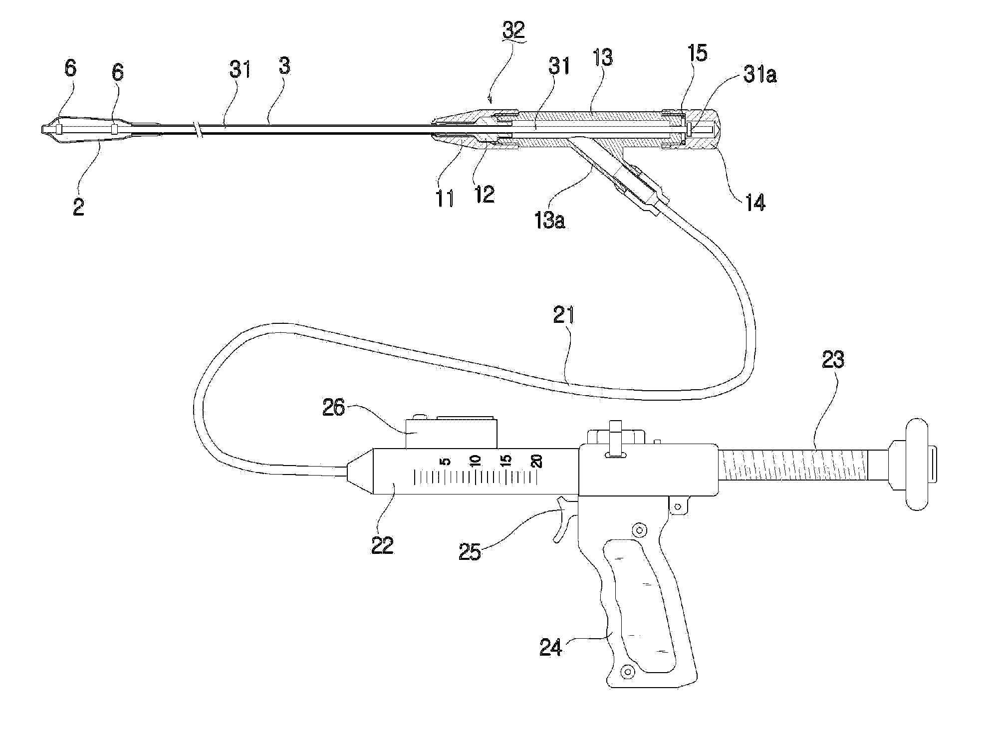
[0038]As shown in FIG. 3, a balloon catheter 30 according to an embodiment of the present invention includes an outer tube 3, a rigid rod 31, a balloon 2, markers 6 and a body unit 32.

[0039]In detail, the rigid rod 31 is inserted into the outer tube 3 along the length of the outer tube 3 such that a gap is defined between the rigid rod 31 and an inner surface of the outer tube 3. Further, the rigid rod 31 is a solid type rod, front and rear ends of which extend outwards from the outer tube 3 by predetermined distances.

[0040]A front end of the balloon 2 is fastened around the front end of the rigid rod 31 and sealed, and a rear end thereof is fastened around a front ...


PUM


Abstract

A balloon catheter is disclosed. The balloon catheter includes an outer tube, a solid rigid rod, a balloon, markers and a body unit. The rigid rod is inserted into the outer tube such that a gap is defined between the rigid rod and the inner surface of the outer tube. The front and rear ends of the rigid rod extend outwards from the outer tube. The front end of the balloon is fastened to the front end of the rigid rod. The rear end of the balloon is fastened to the front end of the outer tube. The markers are fastened to the rigid rod in the balloon at opposite positions spaced apart from each other. The body unit is fastened to the rear end of the outer tube and supports the rigid rod and prevents it from moving forwards.

Description

BACKGROUND OF THE INVENTION[0001]1. Field of the Invention[0002]The present invention relates to a balloon catheter which are used in the medical field and, more particularly, to a balloon catheter which can inflate the interior of a damaged portion, for example, of the spine of a patient, to allow medical cement for recovering the damaged portion to be injected into the damaged portion which is the result of a fracture, necrosis, a dent or the like.[0003]2. Description of the Related Art[0004]Generally, as a surgical procedure of treating, for example, the damaged spine of a patient, there has been a method of inserting a tubular catheter into a patient's body adjacent to the damaged spine of the patient and injecting medical cement into the damaged spine. Sufficiently inflating a damaged portion of the spine and injecting an appropriate amount of medical cement into the inflated portion are factors that are crucial to obtaining a satisfactory result in such surgical procedures usi...

Claims


Application Information

Patent Timeline
Patent Type & Authority Applications(United States)
IPC IPC(8): A61B17/56A61F2/958
CPCA61M25/0102A61M25/1006A61M2025/1079A61M25/10184A61B2017/00557A61B17/0218A61B17/8855A61L29/14A61L2430/38A61B2017/0256A61M25/10182A61M25/10A61L29/04
Inventor CHOI, GIL WOON
Owner CHOI GIL WOON
Why Eureka
Try Eureka