Continuous Variable Valve Duration Apparatus

a technology of continuous variable valve duration and duration, which is applied in the direction of valve arrangements, mechanical equipment, machines/engines, etc., can solve the problems of complex construction of general cvvl and cvvt, and high manufacturing cost, and achieve the effect of simple construction

Active Publication Date: 2013-06-13
HYUNDAI MOTOR CO LTD
View PDF1 Cites 55 Cited by
  • Summary
  • Abstract
  • Description
  • Claims
  • Application Information

AI Technical Summary

Benefits of technology

[0010]Various aspects of the present invention provide for a continuous variable valve duration apparatus which

Problems solved by technology

However, the general CVVL and CVVT are complicated in

Method used


Image

  • Continuous Variable Valve Duration Apparatus
  • Continuous Variable Valve Duration Apparatus
  • Continuous Variable Valve Duration Apparatus

Examples


Embodiment Construction

[0041]Reference will now be made in detail to various embodiments of the present invention(s), examples of which are illustrated in the accompanying drawings and described below. While the invention(s) will be described in conjunction with exemplary embodiments, it will be understood that present description is not intended to limit the invention(s) to those exemplary embodiments. On the contrary, the invention(s) is / are intended to cover not only the exemplary embodiments, but also various alternatives, modifications, equivalents and other embodiments, which may be included within the spirit and scope of the invention as defined by the appended claims.

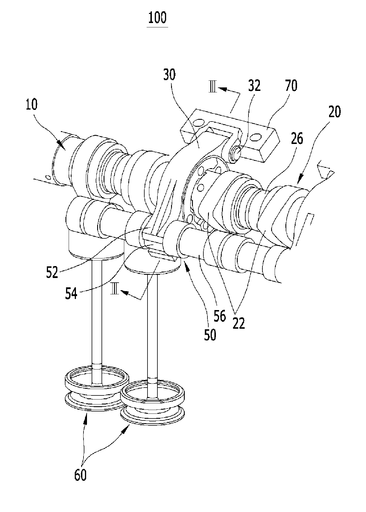
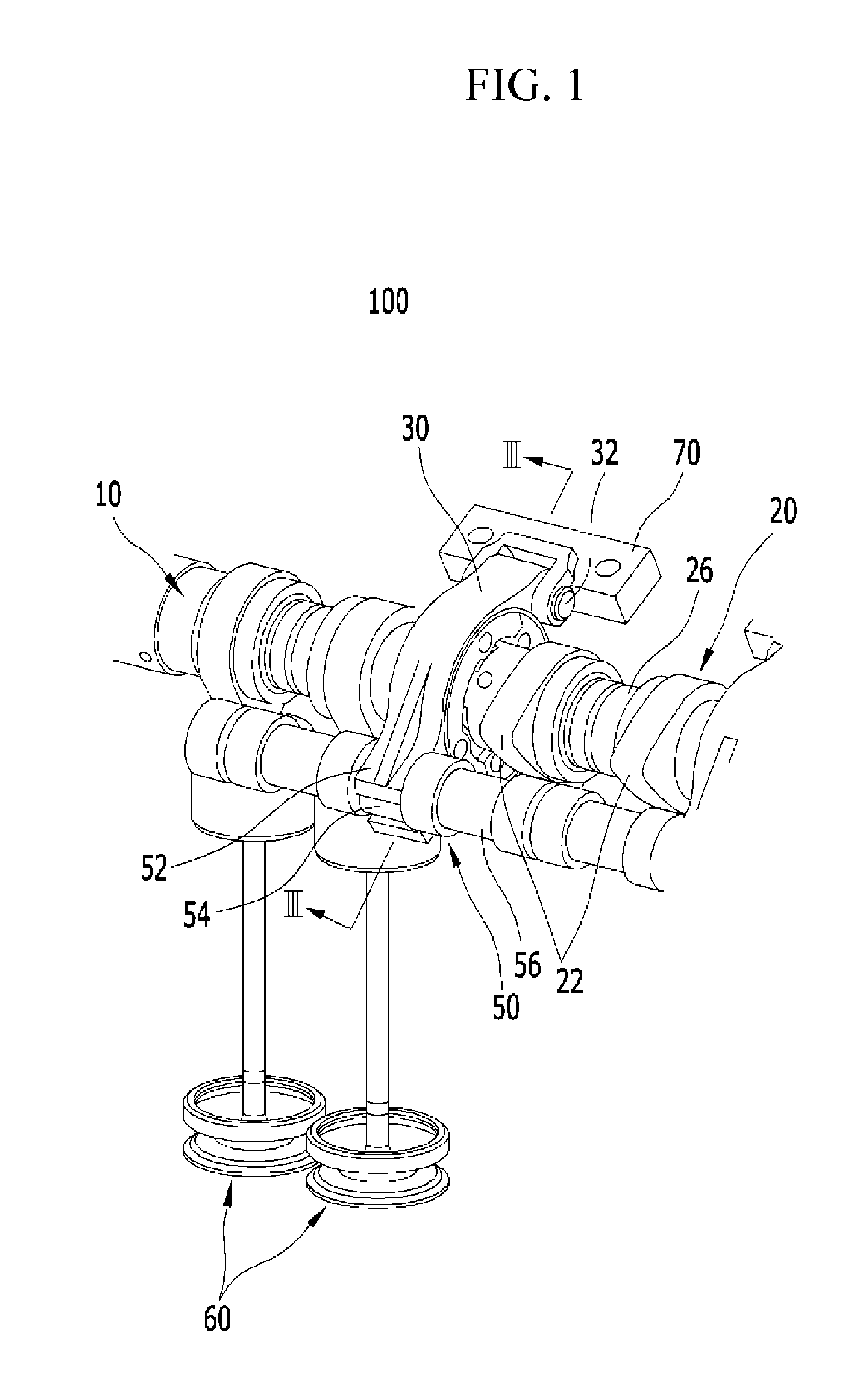
[0042]FIG. 1 is a perspective view of a continuous variable valve duration apparatus according to various embodiments of the present invention, and FIG. 2 is an exploded perspective view of a continuous variable valve duration apparatus according to various embodiments of the present invention.

[0043]FIG. 3 and FIG. 4 are a cross-secti...


PUM


Abstract

A continuous variable valve duration apparatus may vary an opening duration of a valve. The continuous variable valve duration apparatus may include a camshaft in which a camshaft slot is formed, a cam portion of which a cam and a cam slot are formed thereto and of which a rotation center is identical to a rotation center of the camshaft and the cam portion of which a phase angle to the cam shaft is variable, and a duration control portion which varies the phase angle between the camshaft slot and the cam slot.

Description

CROSS-REFERENCE TO RELATED APPLICATION[0001]The present application claims priority of Korean Patent Application Number 10-2011-0130396 filed Dec. 7, 2011, the entire contents of which application is incorporated herein for all purposes by this reference.BACKGROUND OF INVENTION[0002]1. Field of Invention[0003]The present invention relates to a continuous variable valve duration apparatus. More particularly, the present invention relates to a continuous variable valve duration apparatus which may vary opening duration of a valve according to operation conditions of an engine with a simple construction.[0004]2. Description of Related Art[0005]An internal combustion engine generates power by burning fuel in a combustion chamber in an air media drawn into the chamber. Intake valves are operated by a camshaft in order to intake the air, and the air is drawn into the combustion chamber while the intake valves are open. In addition, exhaust valves are operated by the camshaft, and a combus...

Claims


Application Information

Patent Timeline
IPC IPC(8): F01L1/047
CPCF01L1/0532F01L13/0015F01L1/356F01L1/267F01L1/18F01L13/00
Inventor KIM, BACK SIKLEE, SANG HEECHOI, KWANGSOONKIM, JOONG SOOKIM, DAE SUNGIM, HYUKHA, KYOUNG PYO
Owner HYUNDAI MOTOR CO LTD
Why Eureka
Try Eureka