Optical system and method for inspection of patterned samples

Active Publication Date: 2013-06-13
APPL MATERIALS ISRAEL LTD
View PDF2 Cites 6 Cited by
  • Summary
  • Abstract
  • Description
  • Claims
  • Application Information

AI Technical Summary

Benefits of technology

The present invention provides a new optical inspection technique that can optimize the performance of a dark field inspection mode regardless of the actual location of a light collection channel with respect to an illumination / specular reflection azimuth and elevation. This is achieved by appropriately varying the mask pattern, which can include a static pattern or a dynamic pattern. The technique utilizes an illumination and collection masks to optimize light collection with high resolution. The invention is especially useful for inspecting patterned samples having asymmetry along two axes of the sample. The use of multiple illumination apertures and a smaller illumination spot increases accuracy and sensitivity of the inspection.

Problems solved by technology

When dealing with patterns having the pitch size (features) much smaller than the optical spot size on the wafer (diffraction limited spot or optical resolution), BF inspection reaches its limit and certain defects cannot be detected by traditional BF inspection systems.

Method used


Image

  • Optical system and method for inspection of patterned samples
  • Optical system and method for inspection of patterned samples
  • Optical system and method for inspection of patterned samples

Examples


Embodiment Construction

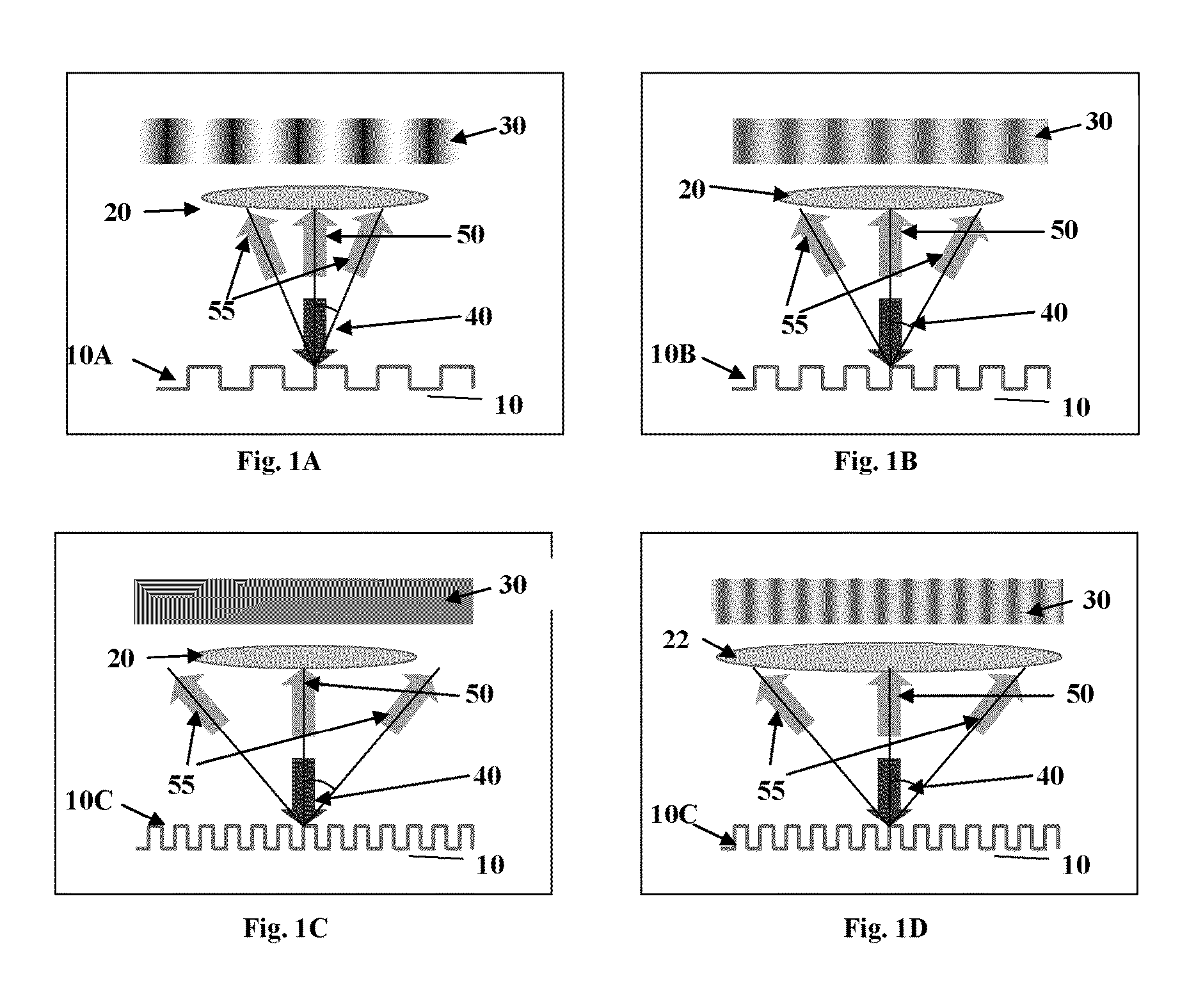
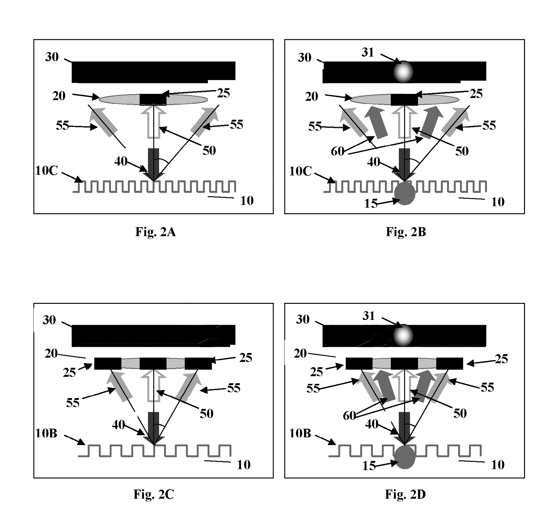
[0047]The general principles of bright field and dark filed inspections of patterned samples are illustrated in FIGS. 1A to 1D and FIGS. 2A to 2D. To facilitate understanding, the same reference numbers are used for identifying components that are common in all the examples.

[0048]It should be noted that, generally, a pattern on the sample's surface may be in a form of a surface relief as shown in FIGS. 1A to 1D, and / or may be defined by regions of different optical properties with respect to given illumination, i.e., regions of different reflection, absorption or transmission properties.

[0049]In FIG. 1A, a sample 10 having a periodic pattern of a certain spatial frequency on its surface 10A is illuminated by an optical beam 40 of a certain wavelength λ (e.g., including ultraviolet and / or infra red illumination) creating an illumination spot on the surface of the sample 10. Light is reflected back from the pattern 10A in different directions according to several diffraction orders. T...


PUM


Abstract

An optical inspection system for inspecting a patterned sample located in an inspection plane includes an illumination unit defining an illumination path, and a light collection unit defining a collection path, each path having a certain angular orientation with respect to the inspection plane. The illumination unit comprises an illumination mask located in a first spectral plane with respect to the inspection plane and the light collection unit comprises a collection mask located in a second spectral plane with respect to the inspection plane being conjugate to the first spectral plane. Arrangements of features of the first and second patterns are selected in accordance with a diffraction response from said patterned sample along a collection channel defined by the angular orientation of the illumination and collection paths.

Description

FIELD OF THE INVENTION[0001]This invention is in the field of optical inspection and relates to a system and method for inspecting patterned samples.BACKGROUND[0002]A decrease in size of the features of a pattern in a semiconductor wafer challenges resolution limits of optical inspection systems. A typical size for features of a pattern corresponding to electronic units is defined by design rules (DRs) of semiconductor wafers.[0003]The shrinking design rules of semiconductor wafers lead to new challenges in optical inspection of the wafer. Pattern inspection techniques typically utilize a so-called bright field (BF) inspection mode.[0004]Traditional BF inspection systems, which are based on resolved imaging of the pattern on a wafer, are limited in their spatial resolution due to diffraction limits of the optics in the imaging system. Using shorter wavelengths, such as the deep ultraviolet (DUV) spectral range, and increasing the numerical aperture (NA) of the imaging system may gen...

Claims


Application Information

Patent Timeline
IPC IPC(8): G01N21/956
CPCG01N21/956G01N2021/8822G01N21/4788H01L22/00
Inventor BERLATZKY, YOAVKOFLER, IDOMESHULACH, DORONBARKAN, KOBI
Owner APPL MATERIALS ISRAEL LTD
Why Eureka
Try Eureka