Machine Tool

a technology of machine tools and tools, applied in the field of machine tools, can solve the problems of reducing machining accuracy, affecting the accuracy of tool positioning control, so as to reduce the displacement of tools due to the machining reaction force, the effect of reducing the displacement of tools

Active Publication Date: 2013-06-13
DMG MORI CO LTD
View PDF3 Cites 9 Cited by
  • Summary
  • Abstract
  • Description
  • Claims
  • Application Information

AI Technical Summary

Benefits of technology

[0009]In order to mitigate the influence of the displacement of the tool (offset from a target control position) due to the machining reaction force, experientially, a process of performing additional cutting through gradual steps such as rough finishing, semi-finishing and finishing or a processing of reducing the machining reaction force by slowing down the feed processing of the feed device has been performed. However, these processes make the machining time of the machine tool longer and therefore improvement in this point has been desired.
[0024]Further, because compensating the displacement amount of the tool due to the machining reaction force suppresses a poor position control accuracy which is caused by the displacement, gradual additional cutting such as rough finishing, semi-finishing and finishing is not necessitated, and if such a gradual machining is performed, machining accuracy thereof can be further improved. Furthermore, because the slowdown of the feed device is not necessitated, a motion control in which acceleration performance of the feed device is utilized to the maximum can be achieved, thereby shortening a moving time of the feed device.
[0026]According to the above configuration, in a case where the drive unit comprises a typical drive motor, the reaction force detecting unit detecting the machining reaction force the tool receives form the workpiece can easily and simply detect the machining reaction force by observing an amount of change of value of a current through the drive motor. Because the detection of the machining reaction force and the correction of the displacement amount due to the machining reaction force are thereby achieved, it is possible to effectively achieve the correction of the displacement amount caused by the machining reaction force in the machine tool without complicating the machine.
[0027]When a workpiece is machined by a tool, it is possible to mitigate the influence of displacement of the tool caused by a machining reaction force the tool receives from the workpiece and achieve a highly accurate machining without necessitating gradual additional cutting and slowdown of a feed device.

Problems solved by technology

This is a serious problem in a case where a tool which is soft and has a small rigidity, such as an elongate end mill, is used as the tool, which leads to a great reduction of machining accuracy.
However, actually, there is never a perfectly rigid body, and therefore, even if the rigidities are increased, a small displacement of the tool always occurs due to the machining reaction force when machining the workpiece.
As a result thereof, the occurrence of reduction of machining accuracy cannot be avoided.
Therefore, no matter how much accuracy of positioning the feed device itself is increased as conventionally, it is not possible to avoid influence of the displacement of the tool caused by the machining reaction force, and therefore improvement of the machining accuracy is limited.

Method used


Image

  • Machine Tool
  • Machine Tool
  • Machine Tool

Examples


Embodiment Construction

[0032]Hereinafter, a first embodiment will be described with reference to the drawings.

1. General Configuration of Machine Tool

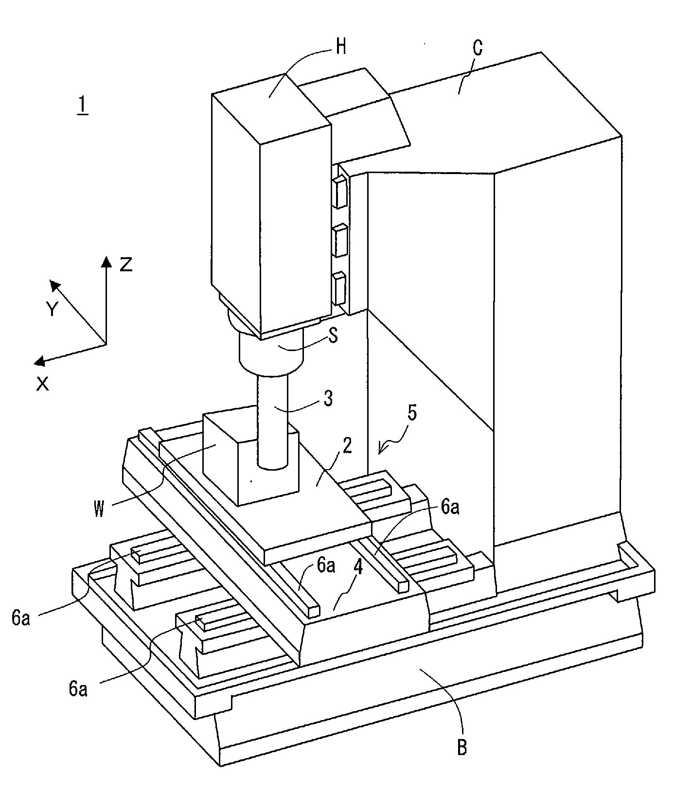
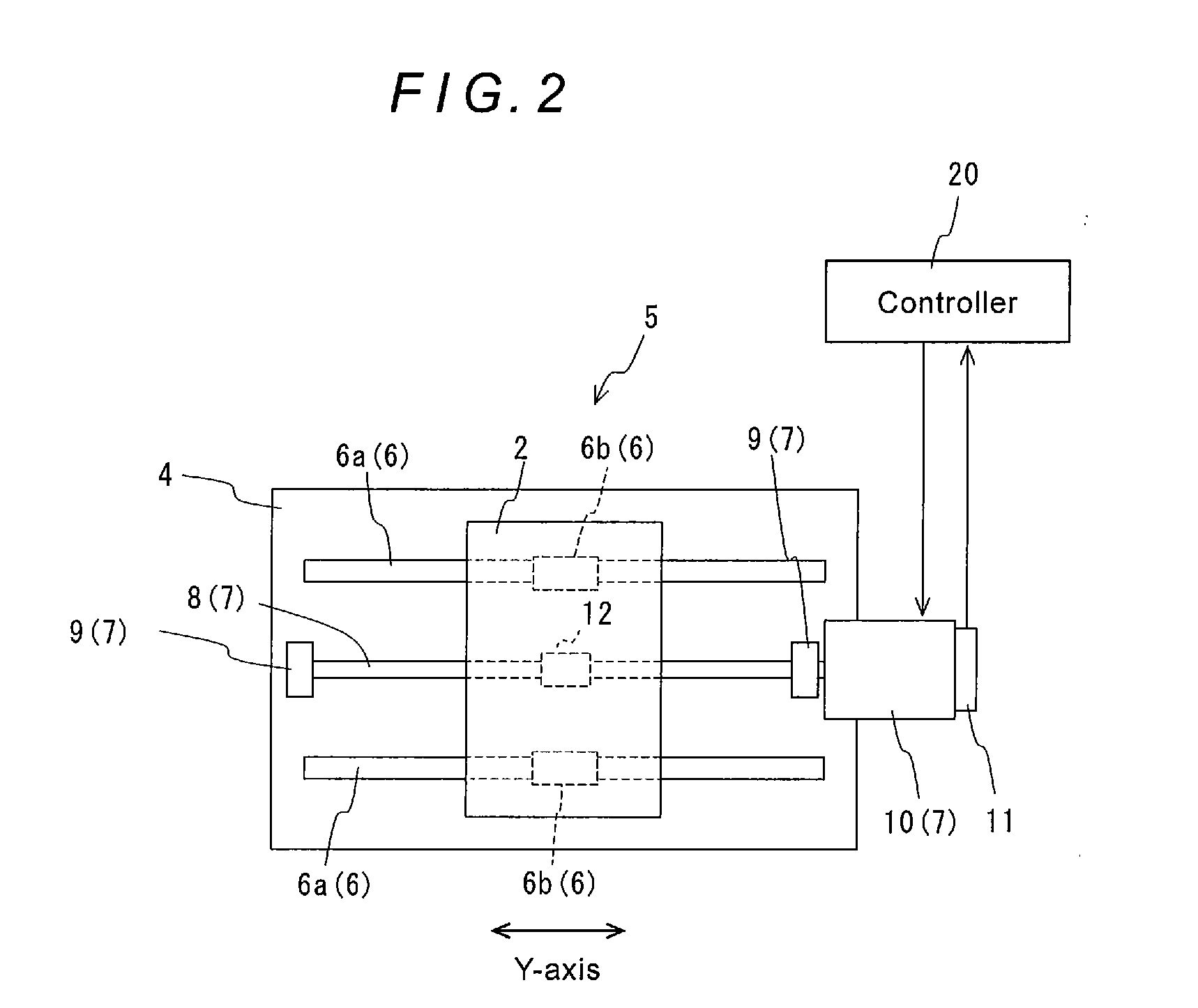
[0033]As shown in FIG. 1, a machine tool 1 of the first embodiment has a table 2 fixedly holding a workpiece W by means of a clamp (not shown), a spindle S to which a tool 3 is attached, a saddle 4 supporting the table 2, and a feed device 5 feeding the table 2 and the saddle 4 in the Y-axis direction and the Z-axis direction shown in the drawing, respectively, by means of a drive motor. The spindle S is mounted to a spindle head H which moves in the Z-axis direction shown in the drawing (in the vertical direction in the drawing) with respect to a column C, and therefore the spindle S is freely slidable in the Z-axis direction. The machine tool 1 controls motions of the feed device 5 and the spindle head H according to a predetermined machining data to machine the workpiece W into a three-dimensional target shape by means of the tool 3. In this embodiment, t...


PUM

PropertyMeasurementUnit
diameteraaaaaaaaaa
diameteraaaaaaaaaa
force detectingaaaaaaaaaa

Abstract

A machine tool has a holding portion, spindle, feed device, controller generating a position control signal according to machining data and controlling a feed motion of a drive unit according to the position control signal, reaction force detecting section for determining a reaction force the tool receives from the workpiece during machining, displacement amount calculating section for determining displacement of the tool with respect to a target control position based on the reaction force, and compensating section receiving the displacement amount and adding correction data for eliminating the displacement amount to the position control signal or the machining data.

Description

TECHNICAL FIELD[0001]The present disclosure relates to a machine tool having a holding portion holding a workpiece and a spindle holding a tool, wherein the machine tool machines the workpiece into a target shape on the basis of machining data.BACKGROUND OF THE DISCLOSURE[0002]In a conventional machine tool, it is known to use a feed device to move a workpiece holding portion relative to a spindle by driving at least one of the workpiece holding portion and the spindle by means of a drive unit. A typical feed device is configured with a guide mechanism for guiding a movable body and a drive mechanism for moving the movable body, and has a configuration in which operation of the drive mechanism is controlled by a controller.[0003]As the guide mechanism, for example, a configuration comprising a slide guide mechanism or a rolling guide mechanism is given, and as the drive mechanism, a configuration comprising a ball screw, a nut screwed onto the ball screw and fixedly provided on the ...

Claims


Application Information

Patent Timeline
Patent Type & Authority Applications(United States)
IPC IPC(8): B23Q15/06
CPCB23Q15/06Y10T409/300896G05B19/404
Inventor KIMURA, AKIRA
Owner DMG MORI CO LTD
Why Eureka
Try Eureka