Standalone flame effect

a flame effect and stand-alone technology, applied in the field of stand-alone flame effects, can solve the problems of large portion of the overall cost of the flame effect system, limiting the breadth with which the flame effect is used, and increasing the cost and complexity of the distribution network

Inactive Publication Date: 2013-06-13
LIVESPARK
View PDF0 Cites 6 Cited by
  • Summary
  • Abstract
  • Description
  • Claims
  • Application Information

AI Technical Summary

Benefits of technology

[0010]A standalone system may advantageously permit the economical deployment of flame effect systems with much more numerous, and potentially smaller, flame effects than traditional flame effects systems. Such a system would have its own advantages over conventional systems, by allowing far more complex visual effects to be produced in fire. A standalone flame system may also be easier, cheaper, and safer to install.

Problems solved by technology

The cost and technical challenges inherent in designing and installing these distribution networks account for a large portion of the overall cost of flame effect systems.
These costs are a major factor that limits the breadth with which flame effects are used.
Further, the costs and complexity of these distribution networks increase as the number of flame effects they are intended to supply increases.

Method used


Image

  • Standalone flame effect
  • Standalone flame effect
  • Standalone flame effect

Examples


Embodiment Construction

[0024]While preferred embodiments of the invention have been shown and described herein, it will be obvious to those skilled in the art that such embodiments are provided by way of example only. Numerous variations, changes, and substitutions will now occur to those skilled in the art without departing from the invention. It should be understood that various alternatives to the embodiments of the invention described herein may be employed in practicing the invention.

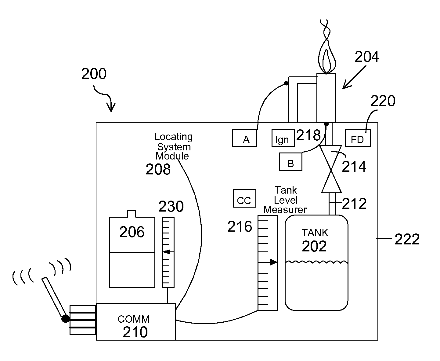
[0025]The invention provides systems and methods for standalone flame effects. Various aspects of the invention described herein may be applied to any of the particular applications set forth below or for any other types of fire displays. The invention may be applied as a standalone system or method, or as part of an integrated display package, such as a theatrical fire display, or any other fire display. It shall be understood that different aspects of the invention can be appreciated individually, collectively, or in c...


PUM


Abstract

The invention provides systems and methods for standalone flame effects. Various aspects of the invention described herein may be applied to any of the particular applications set forth below or for any other types of fire displays. A flame effect may include a local fuel source, a burner configured to receive a flammable fuel from the fuel source, a local power source, and a wireless communication module in electrical communication with the local power source. The location of one or more flame effects may be automatically determined, and may be used in creating a desired fire display.

Description

BACKGROUND OF THE INVENTION[0001]Flame effects used for entertainment purposes before audiences, on stages and otherwise are typically connected to fuel supplies, power supplies and control signal networks with hoses and cables that form bulky and complex networks. The cost and technical challenges inherent in designing and installing these distribution networks account for a large portion of the overall cost of flame effect systems. These costs are a major factor that limits the breadth with which flame effects are used.[0002]Further, the costs and complexity of these distribution networks increase as the number of flame effects they are intended to supply increases. Consequently, flame effects are generally few in number at any given event (less than 100) and are commonly designed to produce large quantities of fire per flame effect to leverage a small number of effects.[0003]Accordingly, it would be desirable to eliminate the need for fuel, power and control signal networks havin...

Claims


Application Information

Patent Timeline
Patent Type & Authority Applications(United States)
IPC IPC(8): F23N1/00F23D14/46F24B1/181F23C5/00
CPCF24B1/181F23N2023/38F23D14/28F23D14/46F24C5/16F24C3/122F23N2223/38
Inventor THIELVOLDT, MIKELEVINE, BRETT
Owner LIVESPARK
Why Eureka
Try Eureka