Pulley structure
- Summary
- Abstract
- Description
- Claims
- Application Information
AI Technical Summary
Benefits of technology
Problems solved by technology
Method used
Image
Examples
first embodiment
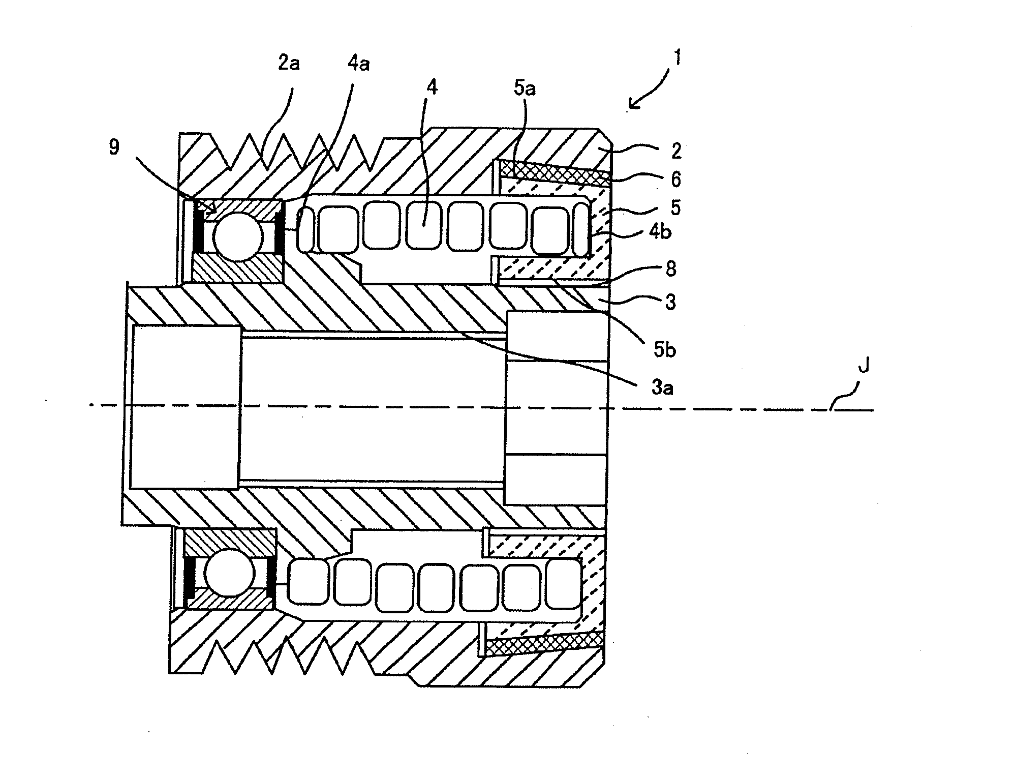
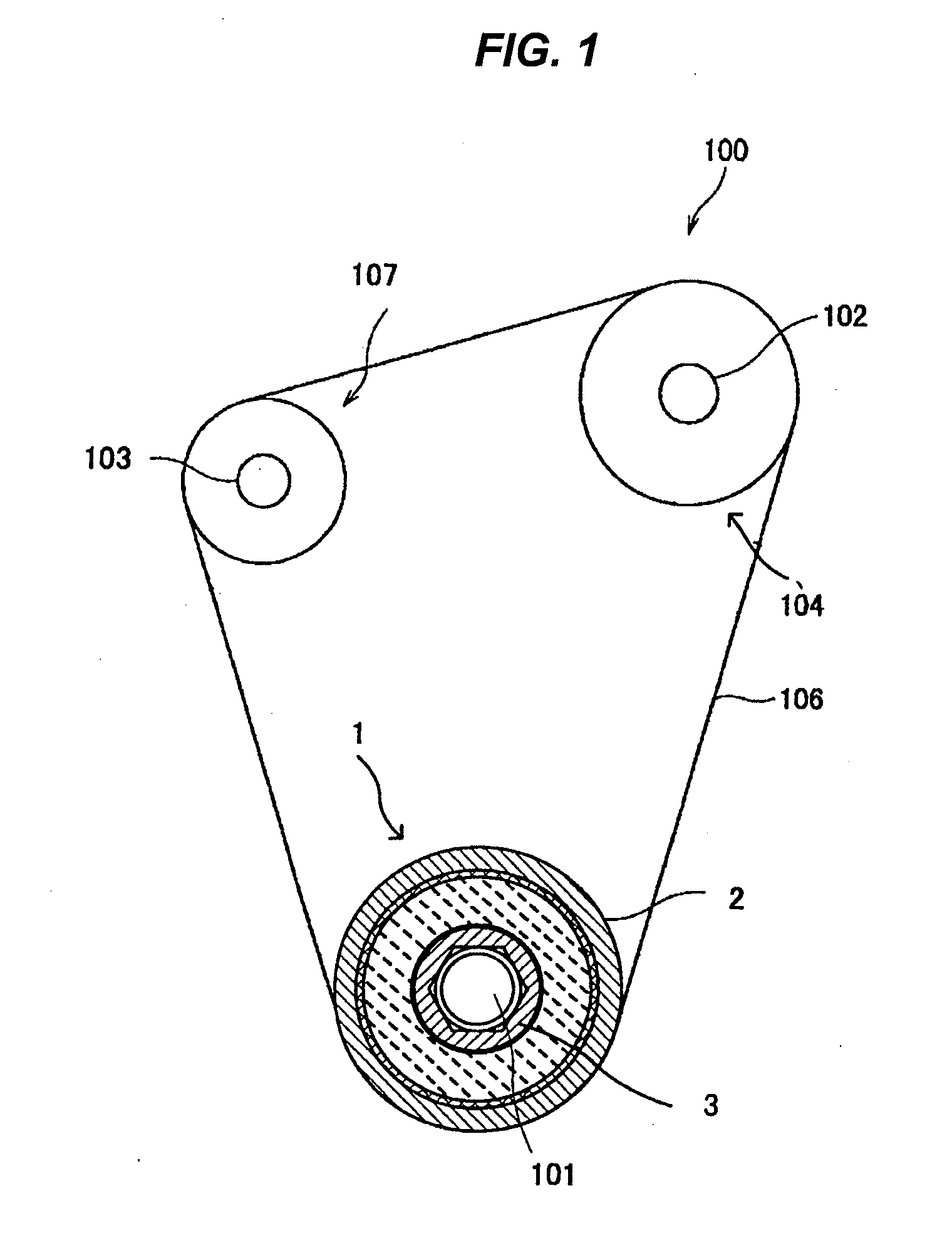
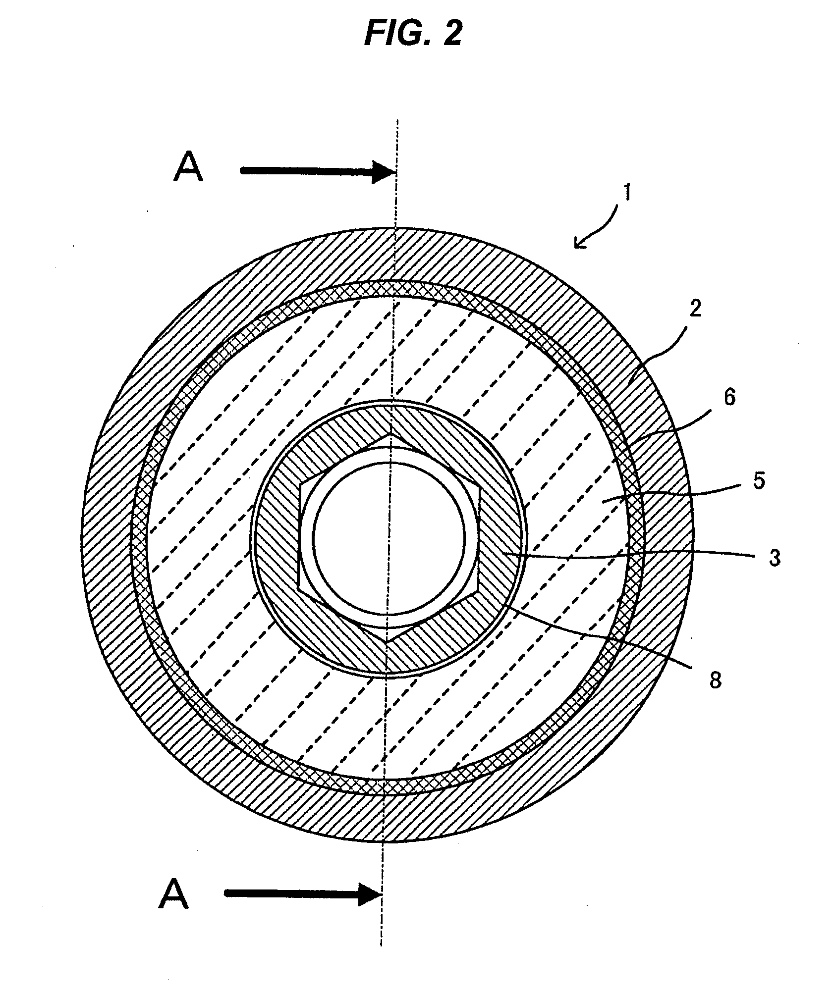
[0027]A first embodiment of the invention will be described. As shown in FIG. 1, this embodiment describes an example where the invention is applied to a drive pulley structure 1 that is used in an auxiliary driving belt system 100 that drives an auxiliary (a water pump or an alternator) by torque of an output shaft 101 of a motor vehicle engine. Note that the drive pulley structure 1 is used to suppress a variation in tension of a transmission belt 106 that is attributed to a change in rotation of the engine.
[0028](Auxiliary Driving Belt System 100)
[0029]FIG. 1 is a schematic block diagram of the auxiliary driving belt system 100 of this embodiment. As is shown in FIG. 1, the auxiliary driving belt system 100 has the drive pulley structure 1 (a pulley structure) that is connected to the output shaft 101 of the engine (a crankshaft of a reciprocating engine or an eccentric shaft of a rotary engine), driven shafts (auxiliary shafts) 102, 103 that are connected to auxiliaries such as ...
second embodiment
[0048]Next, a drive pulley structure 201 according to a second embodiment will be described mainly with respect to different configurations from the first embodiment by omitting the description of similar configurations to those of the first embodiment. FIG. 5 is a plan view of the pulley structure 201. Additionally, FIG. 6 is a sectional view taken along the line B-B that contains a rotational axis J of the drive pulley structure 201 shown in FIG. 5. In addition, FIG. 7 is a diagram showing in detail the drive pulley structure 201 shown in FIG. 6.
[0049](Configuration of Drive Pulley Structure 201)
[0050]As shown in FIGS. 5 and 6, the drive pulley structure 201 has a cylindrical pulley member 202 around which a transmission belt 106 is laid to extend, a hub structure 203 that is connected to an output shaft 101 and which is provided inside the pulley member 202, a coil spring 204 that is fixed to the pulley member 202 at one end 204b thereof, a tapering 205 to which the other end 204...
third embodiment
[0060]Next, a driven pulley structure 301 (a pulley structure) according to a third embodiment will be described mainly with respect to different configurations from the first embodiment by omitting the description of similar configurations to those of the first embodiment. As shown in FIG. 8, the driven pulley structure 301 according to the third embodiment adopts a configuration in which a spring clutch construction is incorporated in a portion where the coil spring 4 of the drive pulley structure 1 is provided in the first embodiment. Additionally, the third embodiment will be described as the driven pulley structure 301 according to the invention being mounted on the driven shaft 102 of the auxiliary driving belt system 100 shown in FIG. 1 for use as a driven pulley structure. FIG. 8 is a sectional view that contains a rotational axis J of the driven pulley structure 301.
[0061](Configuration of Driven Pulley Structure 301)
[0062]In the driven pulley structure 301 according to the...
PUM
 Abstract
Description
Claims
Application Information
 - R&D
- Intellectual Property
- Life Sciences
- Materials
- Tech Scout
- Unparalleled Data Quality
- Higher Quality Content
- 60% Fewer Hallucinations
Browse by: Latest US Patents, China's latest patents, Technical Efficacy Thesaurus, Application Domain, Technology Topic, Popular Technical Reports.
© 2025 PatSnap. All rights reserved.Legal|Privacy policy|Modern Slavery Act Transparency Statement|Sitemap|About US| Contact US: help@patsnap.com


