Auto-Injector

a technology of auto-injector and injection chamber, which is applied in the direction of ampoule syringes, intravenous devices, needles infusion, etc., can solve the problems of user delivery an underdose, injection force may be too high for the user, and the user can deliver an underdose, etc., to achieve less repeatable damping characteristics and hydraulic lock situation

Active Publication Date: 2013-06-13
SANOFI AVENTIS DEUT GMBH
View PDF2 Cites 25 Cited by
  • Summary
  • Abstract
  • Description
  • Claims
  • Application Information

AI Technical Summary

Benefits of technology

[0043]A gasket ring may be arranged to seal the piston against the cylinder in order to avoid uncontrolled leaking of the fluid between the cavities which might lead to less repeatable damping characteristics.
[0044]Another gasket ring may be arranged to seal the connecting rod against the distal end face of the cylinder in order to avoid fluid leaking out of the damper which would otherwise in a drift of the damping characteristics due to disappearing liquid and to pollution of the interior of the auto-injector. An air space may be provided in the...

Problems solved by technology

Administering an injection is a process which presents a number of risks and challenges for users and healthcare professionals, both mental and physical.
There are numerous disadvantages to the user from this approach.
This means that the user can deliver an underdose if the device is not used properly (i.e. the plunger is not fully pressed to its end position).
Injection forces...

Method used


Image

  • Auto-Injector
  • Auto-Injector
  • Auto-Injector

Examples


Embodiment Construction

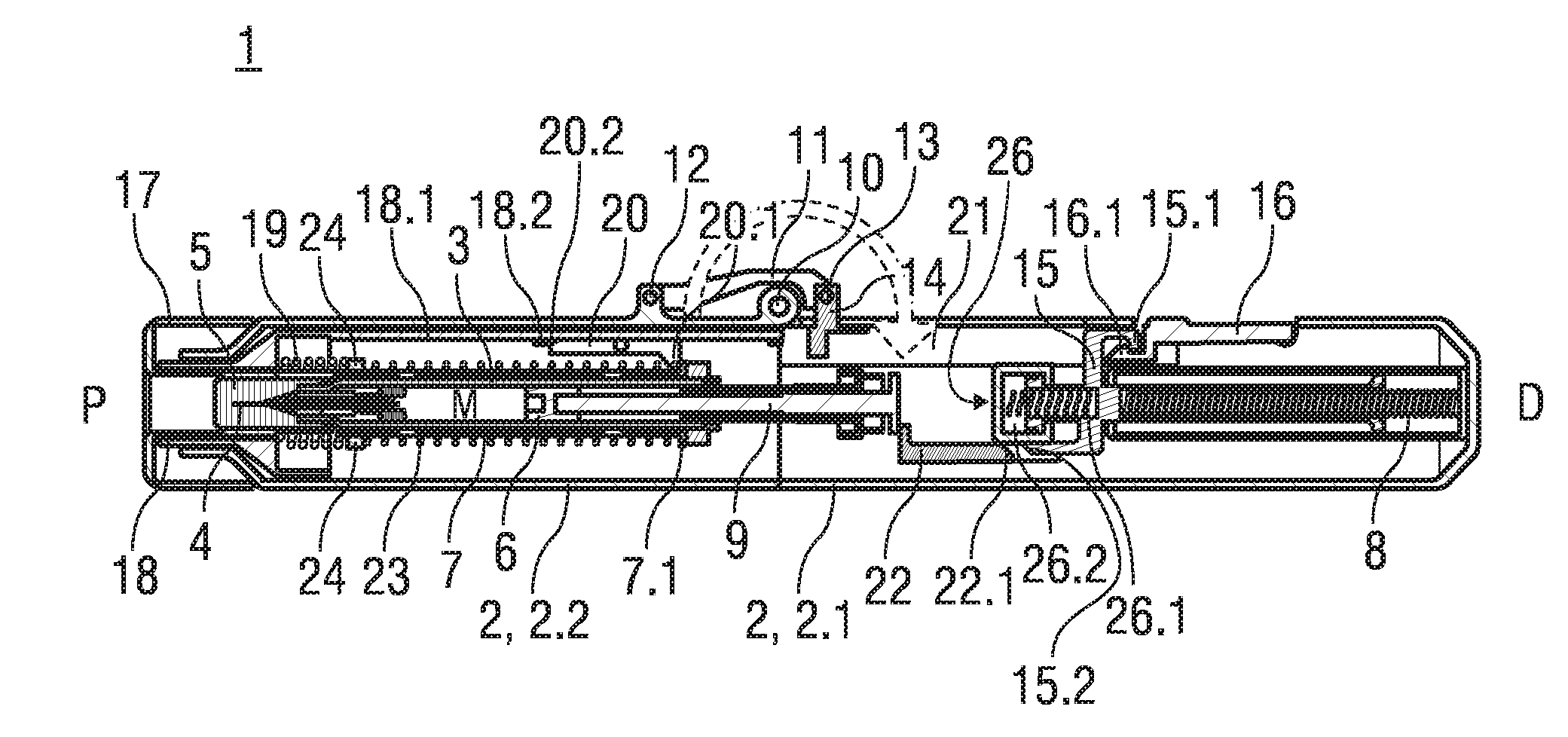
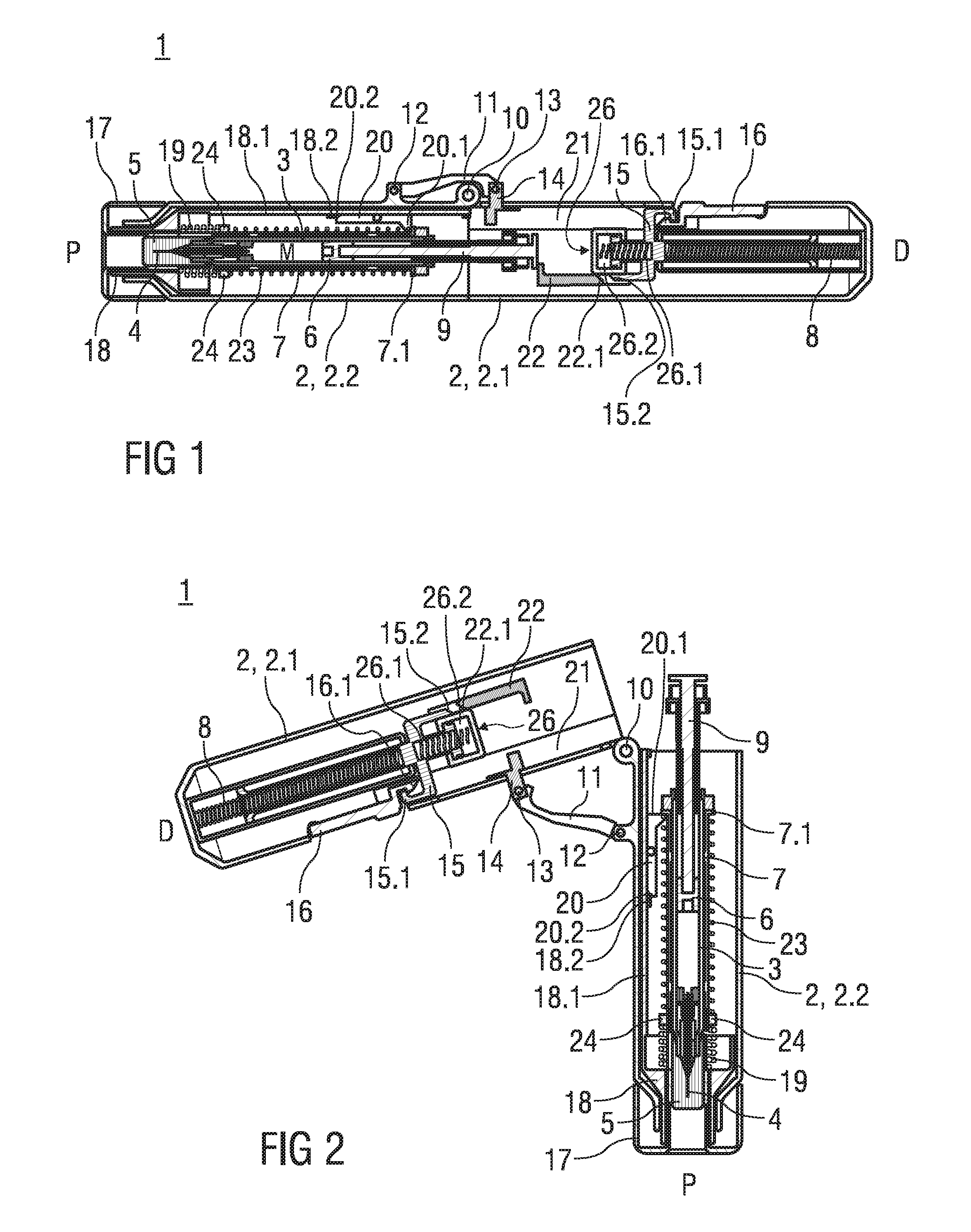
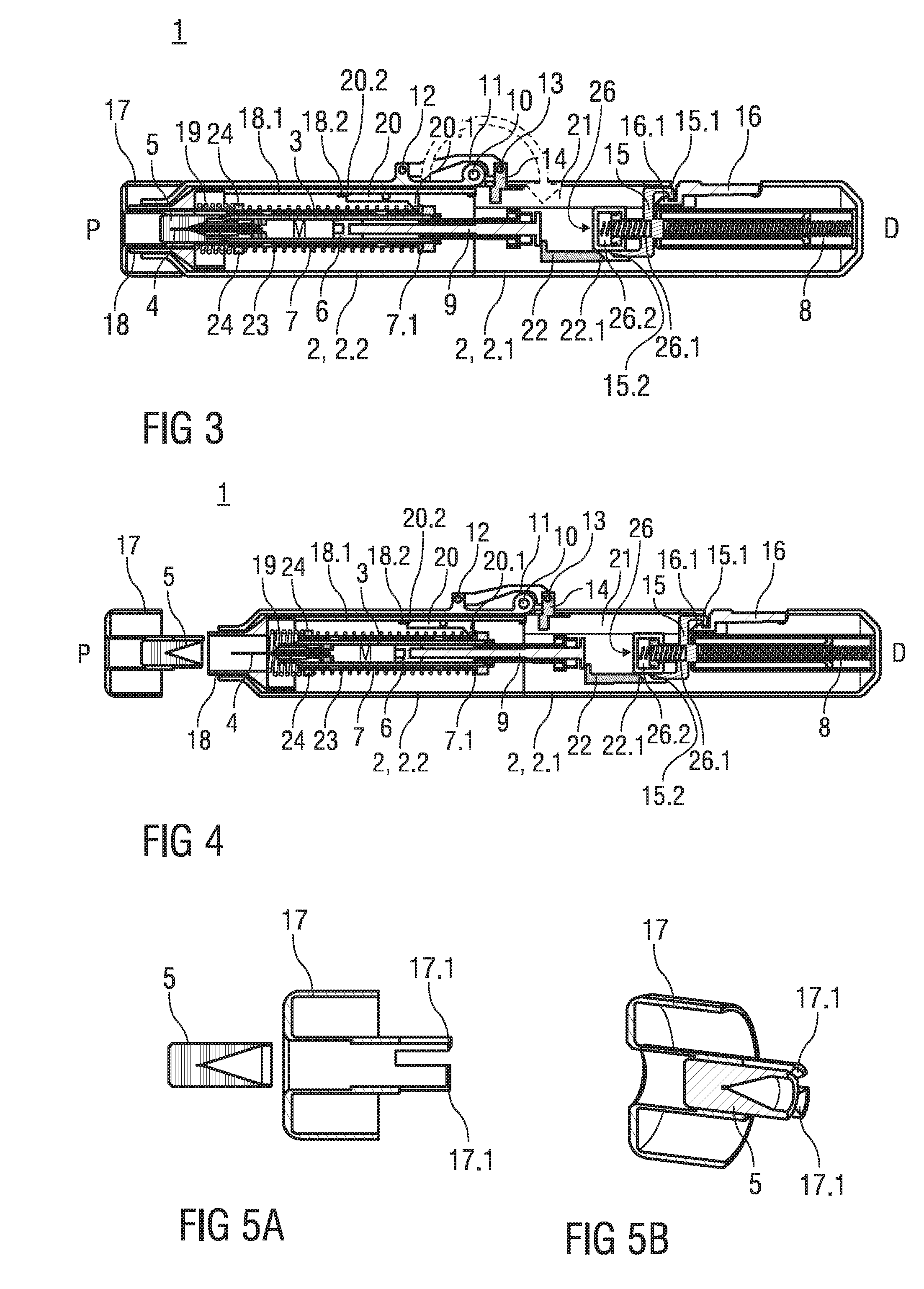
[0135]FIG. 1 is a longitudinal section of a reusable auto-injector 1. The auto-injector 1 comprises an elongate housing 2. A disposable syringe 3, e.g. a Unilife® syringe, with a hollow needle 4 is arranged in a proximal portion of the auto-injector 1. When the syringe 3 is assembled a protective needle shield 5 is attached to the needle 4. A stopper 6 is arranged for sealing the syringe 3 distally and for displacing a liquid medicament M through the hollow needle 4. The syringe 3 is held in a tubular loading bay 7. A drive spring 8 in the shape of a compression spring is arranged in a distal portion of the auto-injector 1. A plunger 9 is arranged for transmitting the spring force of the drive spring 8. The drive spring 8 is used for providing axial motion for advancing the syringe 3, inserting the needle 4 into the injection site, i.e. a patient's skin and injecting a dose of medicament M.

[0136]In the present embodiment the needle 4 is withdrawn into the syringe 3 once fully emptie...


PUM


Abstract

The invention relates to an auto-injector with an interlock mechanism for defining an operation sequence of the auto-injector (1) in a manner to allow a lateral trigger button (16) to be operated only when a proximal end (P) of the auto-injector (1) is pressed against an injection site, wherein a detector means (18) is arranged inside an elongate housing (2) of the auto-injector (1) at the proximal end (P), the detector means (18) slidable in longitudinal direction and biased by a detector spring (19) into a position with the detector means (18) protruding beyond the proximal end (P), wherein a dog (16.2) is arranged at the trigger button (16) and wherein at least one longitudinal bar (18.1, 21) is provided, at least one of the bars (21) slidable in longitudinal direction and coupled to the detector means (18) for joint movement at least in distal direction (D), wherein a recess (21.1) for the dog (16.2) is provided in the bar (21) for allowing the trigger button (16) to be pressed when the detector means (18) is being pushed into the auto-injector (1) and wherein otherwise the dog (16.2) is engaged with the bar (21) in a manner to prevent the trigger button (16) from being pressed.

Description

TECHNICAL FIELD[0001]The invention relates to an auto-injector according to the preamble of claim 1.BACKGROUND OF THE INVENTION[0002]Administering an injection is a process which presents a number of risks and challenges for users and healthcare professionals, both mental and physical.[0003]Injection devices (i.e. devices capable of delivering medicaments from a medication container) typically fall into two categories—manual devices and auto-injectors.[0004]In a manual device—the user must provide the mechanical energy to drive the fluid through the needle. This is typically done by some form of button / plunger that has to be continuously pressed by the user during the injection. There are numerous disadvantages to the user from this approach. If the user stops pressing the button / plunger then the injection will also stop. This means that the user can deliver an underdose if the device is not used properly (i.e. the plunger is not fully pressed to its end position). Injection forces ...

Claims


Application Information

Patent Timeline
IPC IPC(8): A61M5/20A61M5/32
CPCA61M5/2033A61M5/24A61M5/3202A61M5/3204A61M5/3234A61M5/326A61M2005/202A61M2005/208A61M2005/2086A61M2005/2407A61M2005/2496A61M2005/3267A61M2005/206
Inventor KEMP, THOMAS MARKJENNINGS, DOUGLASSCUDAMORE, PETEREKMAN, MATTHEW
Owner SANOFI AVENTIS DEUT GMBH
Why Eureka
Try Eureka