
Method And Computer Program Products For Enabling Supervision And Control Of A Technical System

a technology of computer program and system, applied in the field of human-machine interface, can solve the problems of difficult to readily use information by the operator, large amount of data available, and need to perform several clicking operations

Inactive Publication Date: 2013-06-13
ABB RES LTD
View PDF11 Cites 24 Cited by
  • Summary
  • Abstract
  • Description
  • Claims
  • Application Information

AI Technical Summary

Benefits of technology

The invention provides a way to view a process application while also having access to detailed information and functionality about different parts of the application. The method allows for a balance between an overview picture and specific details about different parts of the application. The operator can easily select different parts of the application and quickly obtain relevant information about them. The invention also allows for an automatic mode to detect and address errors in the process system, providing increased supervision and control. The output of the invention includes a hierarchical display of relevant information, allowing for easy selection of only the information of interest. Overall, the invention provides a convenient and efficient way to view and analyze a process application.

Problems solved by technology

It is inevitable that for large technical systems a huge amount of data is available for being displayed and needs to be monitored by the operator.
A problem in that respect is how to best present the data as visual information to the operator.
However, the screen may be filled with too much information, making it hard for the operator to readily use the information.
In other cases, a disadvantage of currently used supervision systems is the need to perform several clicking operations in order obtain the desired detailed information.

Method used


Image

  • Method And Computer Program Products For Enabling Supervision And Control Of A Technical System
  • Method And Computer Program Products For Enabling Supervision And Control Of A Technical System
  • Method And Computer Program Products For Enabling Supervision And Control Of A Technical System

Examples


Embodiment Construction

[0040]In the following, same reference numerals are used throughout the drawings for denoting same or corresponding parts.

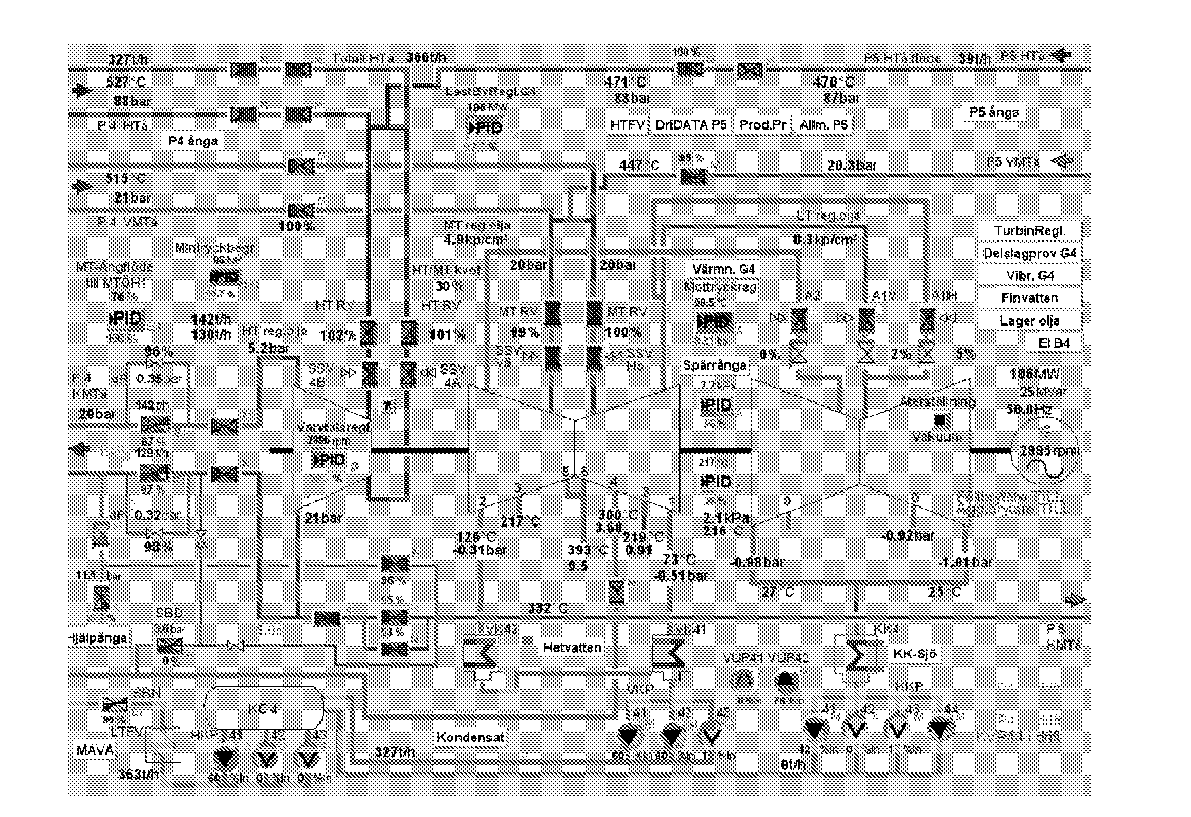
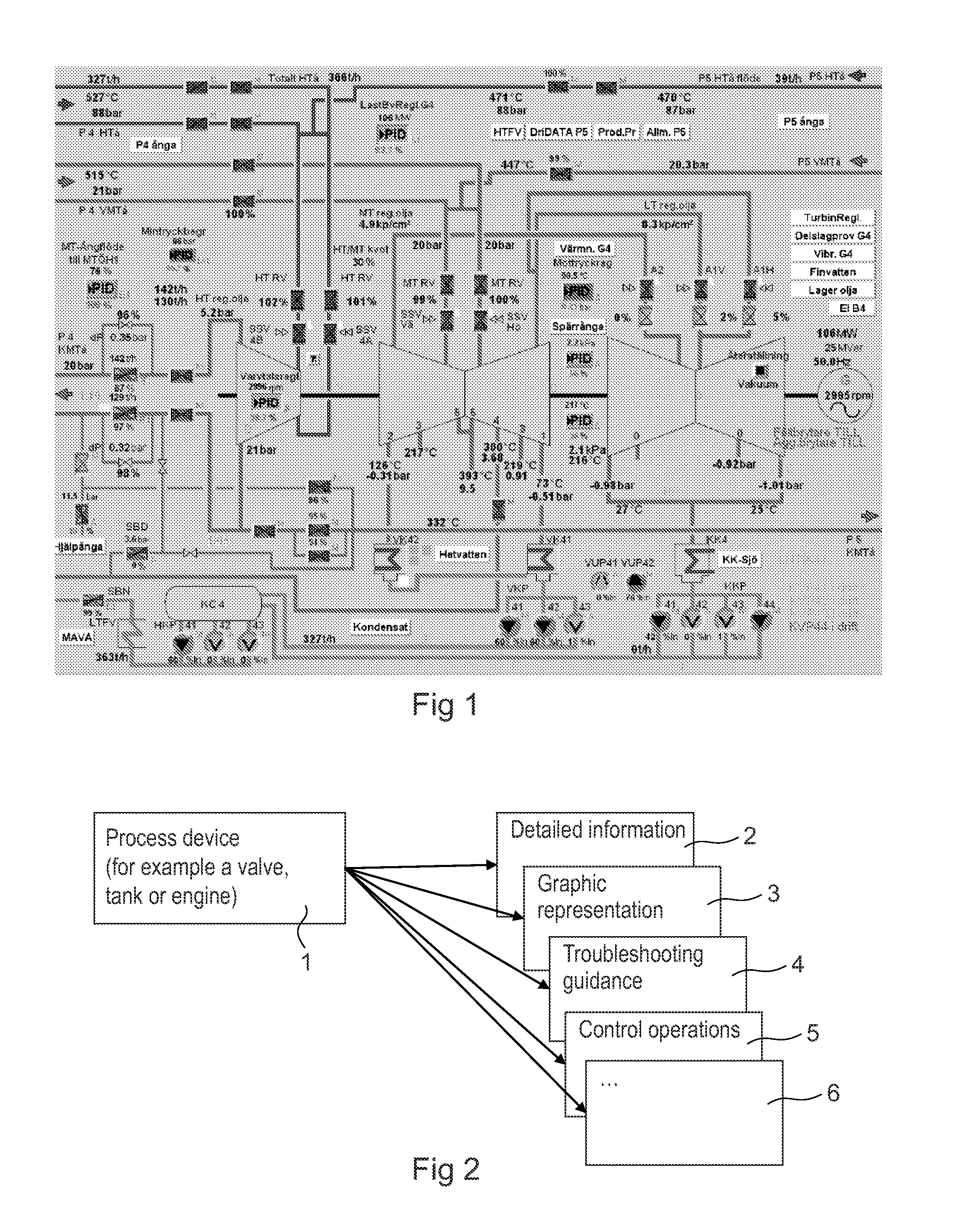
[0041]In order to provide a more thorough understanding of the invention, and for comparison, a known way of presenting data is illustrated in FIG. 1. FIG. 1 shows a screenshot of a typical HMI display view over a process application that is being supervised by an operator. In particular, a typical SCADA overview is illustrated. As can be seen, there is a vast amount of information and functionality available, making it hard for the operator to obtain a good overview.

[0042]Briefly, in accordance with the present invention, different “lenses” in combination with a “magic sight” are provided. The different lenses refer to different types of information and functionality that a graphical object corresponding to a real device in the process industry provides. The magic sight is a visual reference tool that the operator uses to navigate and zoom into information and d...


PUM


Abstract

A method for enabling supervision and control of a technical system, the method being implemented in a supervisory control system including a display unit. The display unit displays an HMI display view over a process application of the technical system, the HMI display view including one or more graphical process objects representing physical process devices of the process application of the technical system. The method includes the steps of: providing on the HMI display view a visual reference; receiving input signals indicating, in the visual reference, a selection of one of the graphical process objects; and in response to receiving the input signals outputting, in the HMI display view, one or more lens views, each of the lens views corresponding to a particular type of information or functionality relating to the selected graphical process object. The invention further relates to computer program products.

Description

FIELD OF THE INVENTION[0001]The invention relates generally to the field of supervision, control and monitoring of technical systems or processes, and in particular to human-machine interfaces for such supervision, control and monitoring.BACKGROUND OF THE INVENTION[0002]In a typical process industry comprising automated processes, such as petrochemical, chemical or pharmaceutical processing systems, pulp and paper production systems or power plants, there is a need to monitor various process variables and control the processes accordingly.[0003]Supervision or monitoring of such technical systems is of great importance for ensuring proper functioning of the technical system and for enabling right action to be taken. It is important that the monitoring allows an operator to quickly detect any fault conditions and also to rapidly act upon such fault conditions.[0004]The general task of supervision results in the same kind of problems for the operator, as described below, independently ...

Claims


Application Information

Patent Timeline
IPC IPC(8): G05B15/02
CPCG05B15/02G05B19/048
Inventor TIMSJO, SUSANNEOLAUSSON, MARTIN
Owner ABB RES LTD
Learn More