Method and system for generating cutting paths

a cutting path and cutting technology, applied in the direction of programme control, automatic control devices, milling equipment, etc., can solve problems such as inefficiency removal, and achieve the effect of increasing the curvature radius

Active Publication Date: 2013-06-13
DELCAM
View PDF11 Cites 23 Cited by
  • Summary
  • Abstract
  • Description
  • Claims
  • Application Information

AI Technical Summary

Benefits of technology

[0055]Conveniently, the method may increase the radius of curvature of portions of the preceding cutting path if is determined that the angle of engagement falls above the predetermined angle.
[0056]The method may ensure that each of the cutting paths is tangent continuous. That is, the method may obtain the tangent (ie the first derivative) of the curve of the cutting path and determine whether that is continuous for that cutting path. Such a step is convenient because it can help to ensure that a machine tool can perform that cutting path.

Problems solved by technology

Typically, corners of a model cause problems for the material removers of a machine tool in that there is often problem material left adjacent the corner which is often not efficiently removed.

Method used


Image

  • Method and system for generating cutting paths
  • Method and system for generating cutting paths
  • Method and system for generating cutting paths

Examples


Embodiment Construction

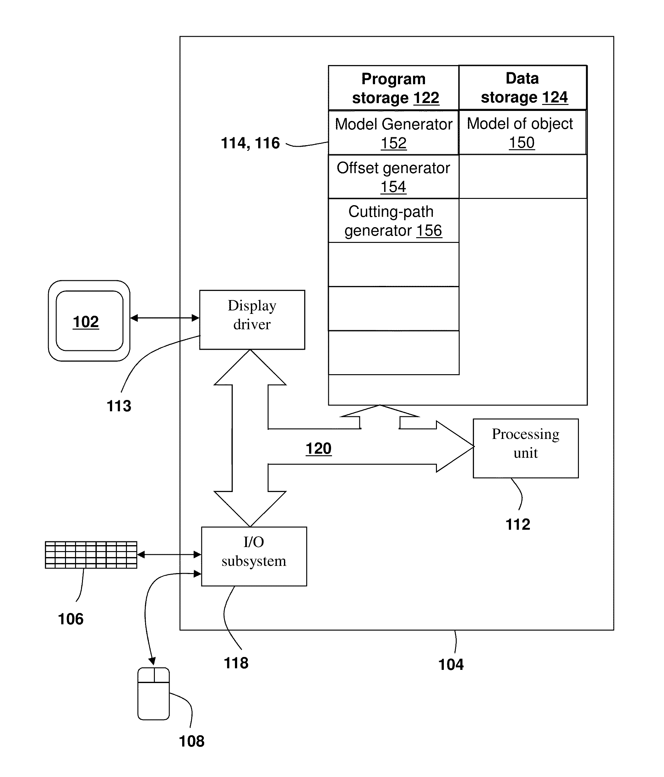
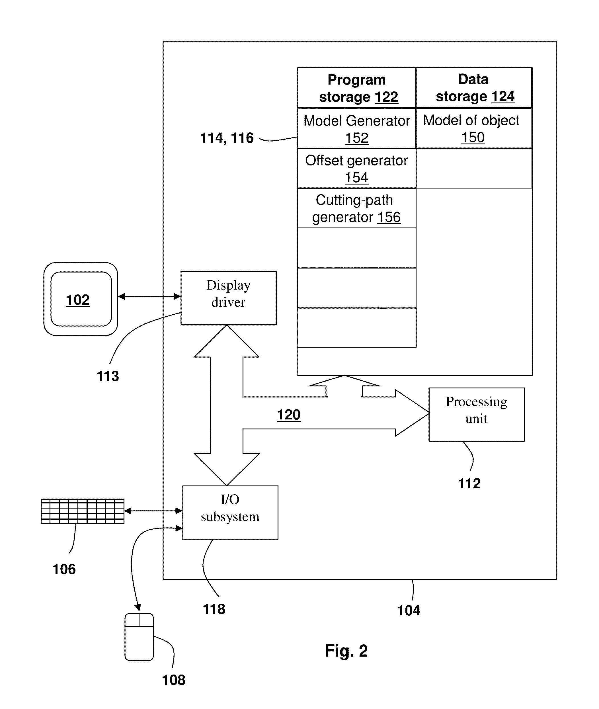
[0107]The computer system of FIG. 2 comprises a display 102, processing circuitry 104, a keyboard 106 and a mouse 108. The processing circuitry 104 comprises a processing unit 112, a graphics system 113, a hard drive 114, a memory 116, an I / O subsystem 118 and a system bus 120. The processing unit 112, graphics system 113 hard drive 114, memory 116 and I / O subsystem 118 communicate with each other via the system bus 120, which in this embodiment is a PCI bus, in a manner well known in the art.

[0108]The graphics system 113 comprises a dedicated graphics processor arranged to perform some of the processing of the data that it is desired to display on the display 102. Such graphics systems 113 are well known and increase the performance of the computer system by removing some of the processing required to generate a display from the processing unit 112.

[0109]It will be appreciated that although reference is made to a memory 116 it is possible that the memory could be provided by a vari...


PUM


Abstract

A method of generating a plurality of cutting paths for a material remover, which generates a set of offsets from the perimeter of the model for each corner region of the model; creates, for each offset within each of the sets, a subset of cutting paths based upon each offset with each cutting path within the subset separated from a neighbouring cutting path within the subset by a stepover, wherein a portion of a first cutting path in one of the subsets has a distance of greater than the stepover to the last cutting path in a previous subset; joins cutting paths from within a subset at each corner region forming complete cutting paths causing a material remover to move between corner regions; and creates backfill cutting paths used to remove material from between subsets of cutting paths in the portion greater than the stepover between the subsets.

Description

FIELD OF THE INVENTION[0001]This invention relates to methods and systems for generating cutting paths. In particular, but not exclusively, the invention relates to methods of making generation of cutting paths more efficient and / or capable of being performed by machine tools.BACKGROUND OF THE INVENTION[0002]Computer Numerically Controlled (CNC) machines are well known. Such CNC machines typically control a material remover and include milling machines having various numbers of axes about which the material remover can be moved. In such milling machines, the material remover is a rotating element that is moved across the block of material from which a part is being manufactured.[0003]As such, the CNC machine has, what may be referred to as, a cutting path programmed into it along which the material remover is moved. It will be appreciated that the length of time that it takes to make a part from the block of material is governed by the length of the path and the speed at which the m...

Claims


Application Information

Patent Timeline
Patent Type & Authority Applications(United States)
IPC IPC(8): G06F17/00
CPCG06F17/00G05B19/4093G05B2219/45145G05B2219/35159G05B2219/36266G05B19/4097Y02P90/02B23C3/00B23Q15/14G05B19/40937G05B19/19
Inventor MACKMAN, STEPHEN WILLIAM
Owner DELCAM
Why Eureka
Try Eureka