
Chemical-mechanical polishing pad conditioning system

a technology of conditioning system and polishing pad, which is applied in the field of chemical-mechanical polishing, can solve the problems of waste of consumables, and waste of valuable machine time, and achieve the effect of increasing the radius of curvature of asperities and cutting further the conditioning tim

Active Publication Date: 2011-10-06
MASSACHUSETTS INST OF TECH
View PDF6 Cites 0 Cited by
  • Summary
  • Abstract
  • Description
  • Claims
  • Application Information

AI Technical Summary

Benefits of technology

[0007]In another aspect, the invention is a method for conditioning a polishing pad having asperities with a small radius of curvature including rotating the polishing pad while in contact at a selected pressure at an interface with a rotating and translating bulk material containing passages through which a slurry is passed to the interface to increase the radius of curvature of the asperities.

Problems solved by technology

This procedure is very inefficient because the CMP polishing tool was designed with the sole purpose of polishing wafers, not conditioning polishing pads.
Therefore, valuable machine time and costly consumables (i.e., wafers and environmentally-harmful slurry) are wasted.

Method used


Image

  • Chemical-mechanical polishing pad conditioning system
  • Chemical-mechanical polishing pad conditioning system
  • Chemical-mechanical polishing pad conditioning system

Examples


Embodiment Construction

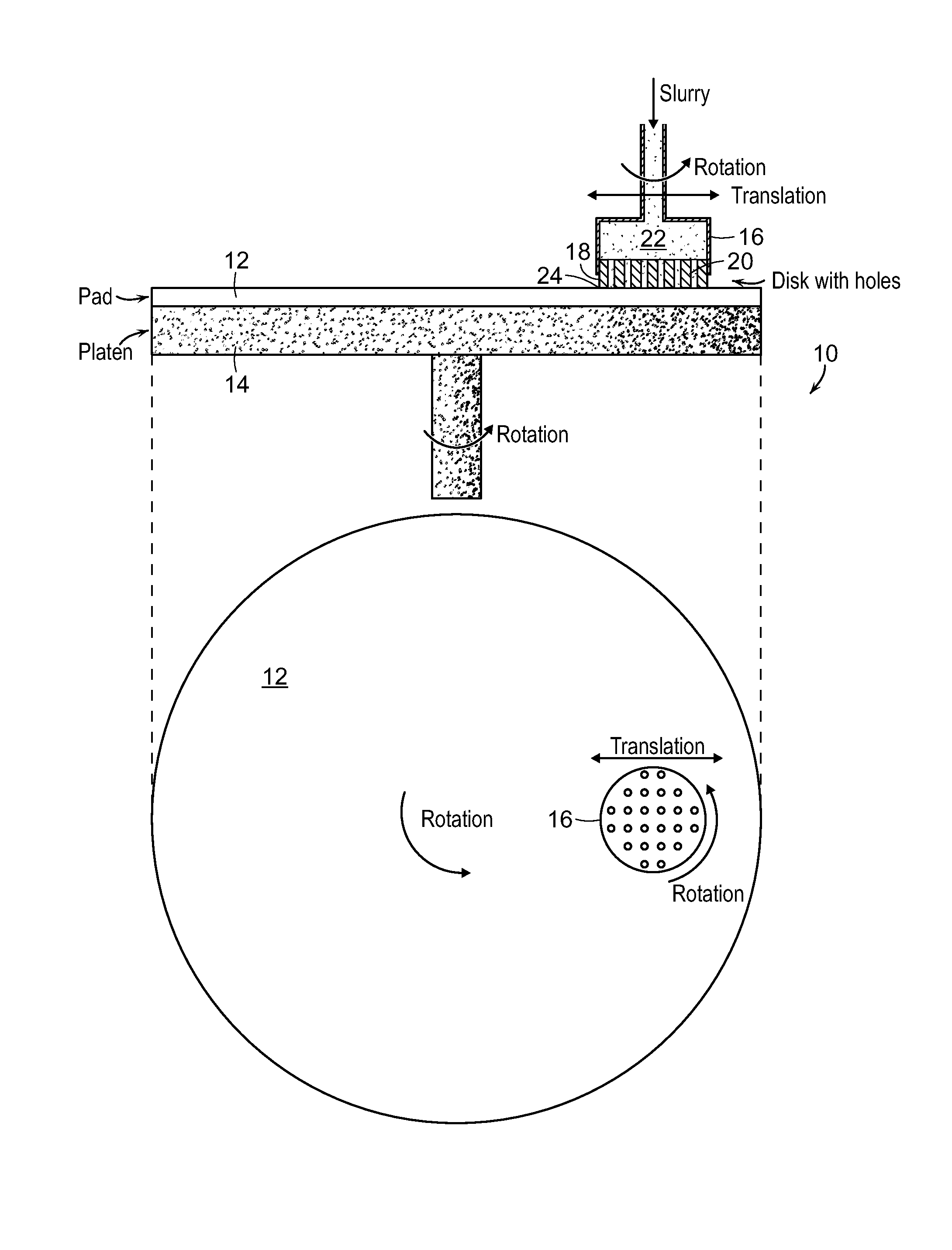
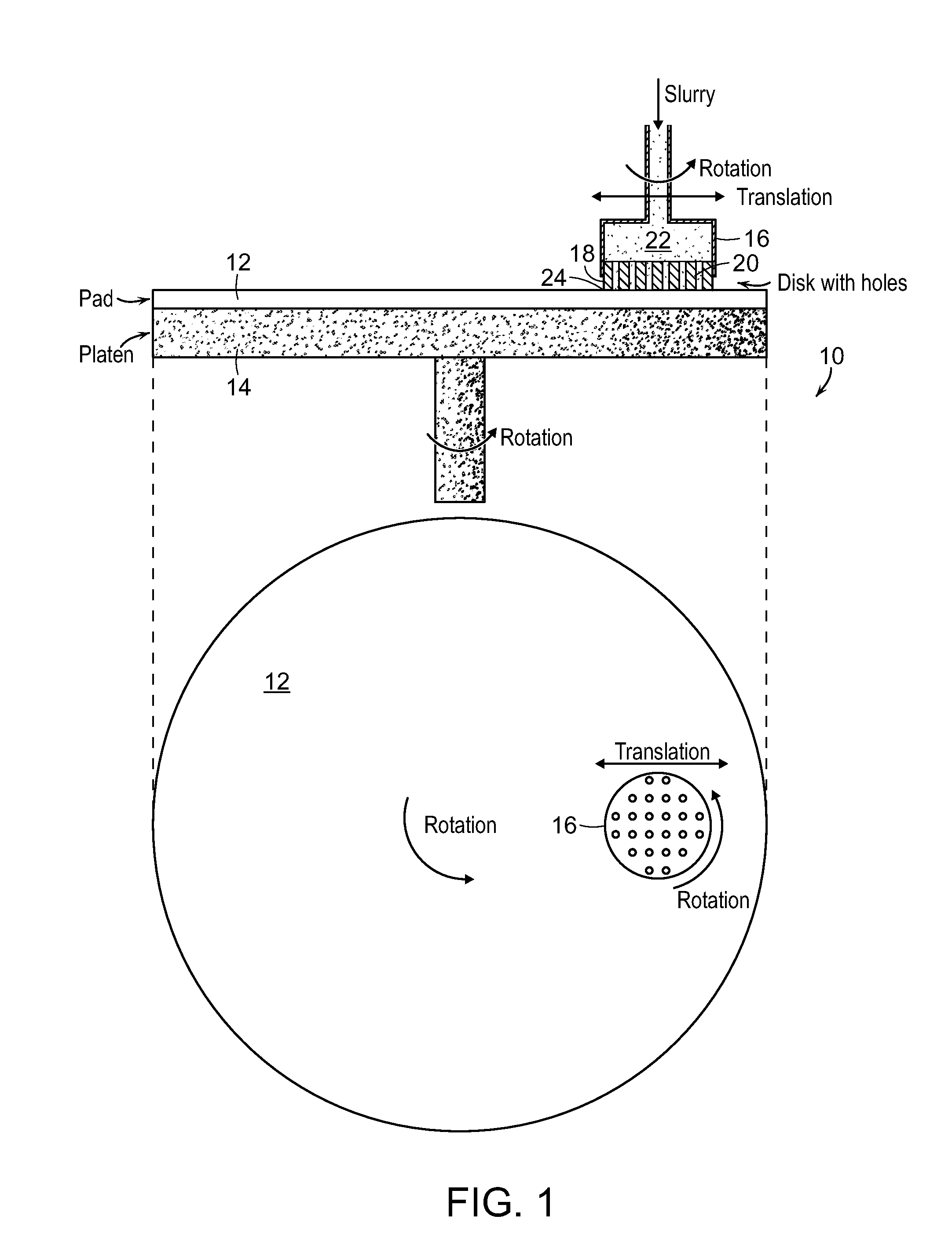
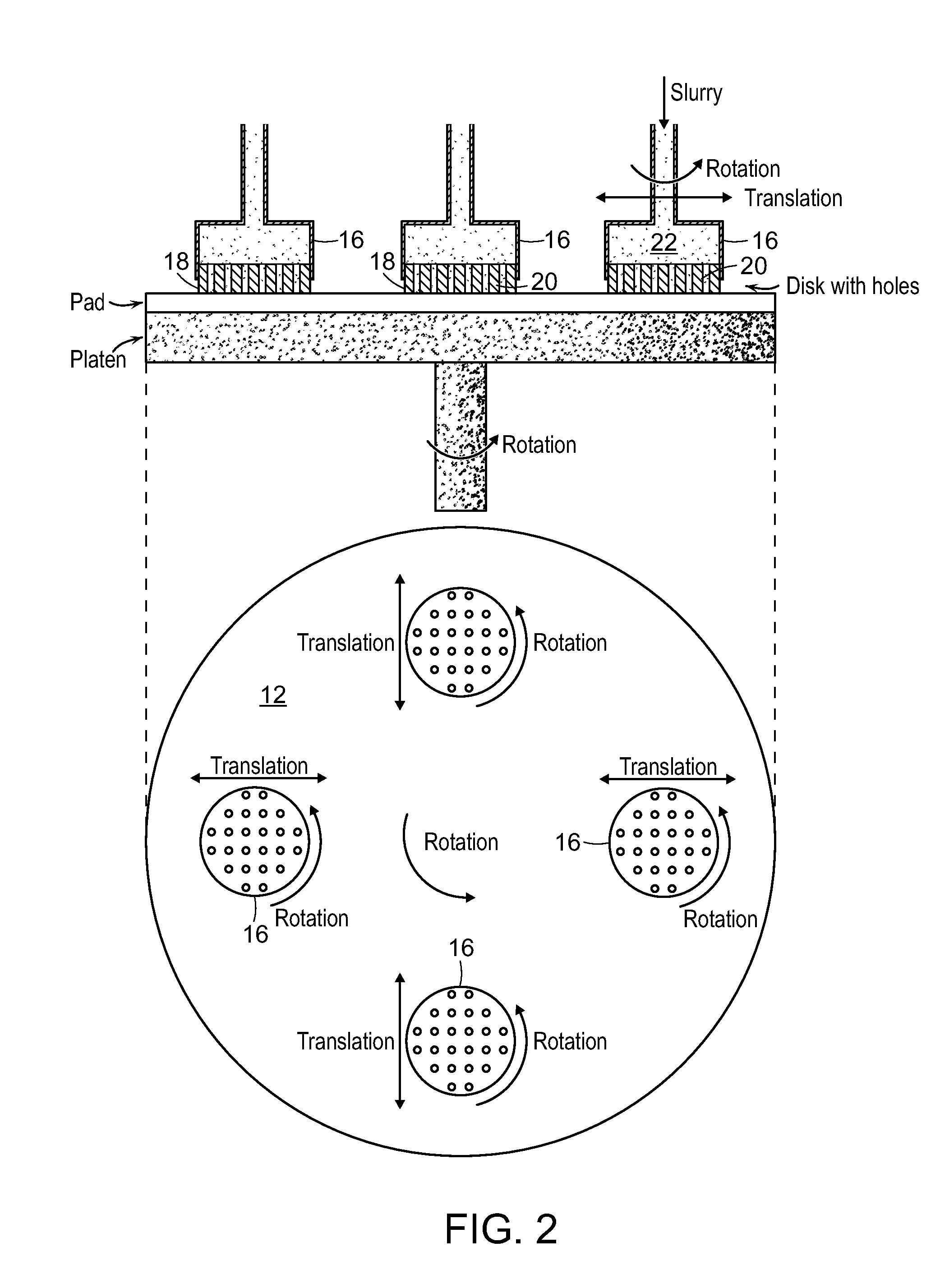
[0012]With respect to FIG. 1, a polishing pad conditioning system 10 includes a pad 12 to be conditioned. Polishing pads 12 are often made of polyurethane. The pad 12 is supported on a rotatable platen 14. Another platen 16 supports a disk 18 of bulk material such as metal or a ceramic. The bulk material 18 includes holes 20 through which a slurry 22 is pumped to an interface 24 between the bulk material 18 and the pad 12. It is preferred that the platen 16 not only be capable of rotating but also of translation as shown in FIG. 1.

[0013]As mentioned above, approximately 50 Cu-coated wafers are polished, and then discarded, to condition a pad according to the prior art technique. Each such wafer has a Cu coating having a thickness of about 1 μm so that the total thickness of Cu polished away to condition one pad is approximately 50 μM. Thus if a Cu disk is used in the present invention, approximately 50 μm of the disk will be worn away. If the same disk is used 20 times, then about a...


PUM

PropertyMeasurementUnit
pressureaaaaaaaaaa
pressureaaaaaaaaaa
pressureaaaaaaaaaa

Abstract

Polishing pad conditioning system. The system includes a first rotatable platen supporting a polishing pad containing asperities having a radius of curvature. A second rotatable platen supports a disk of bulk material having holes therethrough, the second rotatable platen supported for translation as well as rotation. Means are provided for pushing the polishing pad and bulk material into contact at an interface during rotation and translation and means are provided for passing a slurry through the holes in the bulk material to the interface whereby the radius of curvature of the pad asperities is increased. Water may be delivered to the bulk material for cooling. A process for conditioning a polishing pad is also disclosed.

Description

BACKGROUND OF THE INVENTION[0001]This invention relates to chemical-mechanical polishing (CMP) and more particularly to a dedicated polishing pad conditioning machine.[0002]Chemical-mechanical polishing is a process used by semiconductor manufacturers to planarize the surface of an integrated circuit so that the chip can have multiple, flat layers. During the CMP process, a machine is used to press a wafer and a polishing pad into contact at a selected pressure. Both the pad and the wafer are turned at a given rotational velocity and a slurry containing a liquid and abrasive particles is pumped into the interface of the pad and the wafer to increase the material removal rate. In order for the CMP process to be effective, defects on the wafer surface must be kept to a minimum. Recently, scratching of the wafer surface has emerged as the dominant defect during CMP. The inventors have shown that the primary source of scratching is polishing pad asperities and not due to agglomerated sl...

Claims


Application Information

Patent Timeline
Patent Type & Authority Applications(United States)
IPC IPC(8): B24B1/00B24B21/18
CPCB24B53/017
Inventor SAKA, NANNAJIEUSNER, THORCHUN, JUNG-HOON
Owner MASSACHUSETTS INST OF TECH
Learn More