
Method and system for power control of electrical devices using maximum power control algorithm

a technology of power control algorithm and power control method, which is applied in non-electric variable control, process and machine control, instruments, etc., can solve the problems of increased power consumption, reduced power consumption, and change in electricity costs in real tim

Active Publication Date: 2013-06-13
KT CORP
View PDF5 Cites 26 Cited by
  • Summary
  • Abstract
  • Description
  • Claims
  • Application Information

AI Technical Summary

Benefits of technology

The patent text describes a method, system, and computer program for controlling the power demand of electrical devices in a building or home by controlling the time and amount of power and renewable energy used. The technical effect of the patent text is to provide a way for power providers to manage peak power demand from multiple electrical devices, ultimately reducing the strain on the power grid. The method involves analyzing power usage patterns and scheduling the use of power to avoid exceeding predetermined limits. Overall, the patent aims to create a more efficient and reliable power control system.

Problems solved by technology

When such smart grid is installed, electricity costs change in real time depending on power consumption and consumers control energy consumption according to the changing electricity costs.
For example, the electricity costs are lower during late night hours when power consumption is low and is higher during daytime peak hours when people's activities cause greater power consumption.
This may lead to customers, who for example, charge an electric car during the late night hours when the electricity costs are lower.
However, there is a problem in that the load that can be controlled by the maximum demand power controller is limited to, for example, an air conditioner, a refrigerator, or air conditioning equipment in a building.
Moreover, a one-way control approach to control the peak power by simply cutting off power is inconvenient to the user.

Method used


Image

  • Method and system for power control of electrical devices using maximum power control algorithm
  • Method and system for power control of electrical devices using maximum power control algorithm
  • Method and system for power control of electrical devices using maximum power control algorithm

Examples


Embodiment Construction

[0029]Exemplary embodiments are described in detail with reference to the accompanying drawings in detail. The same reference numbers are used throughout the drawings to refer to the same or like parts. Detailed descriptions of well-known functions and structures incorporated herein may be omitted to avoid obscuring the subject matter of the exemplary embodiments.

[0030]Exemplary embodiments relate to a method and a system for power control of an electrical device, and more particularly, exemplary embodiments suggest a method and a system for power control of an electrical device based on maximum power usage time.

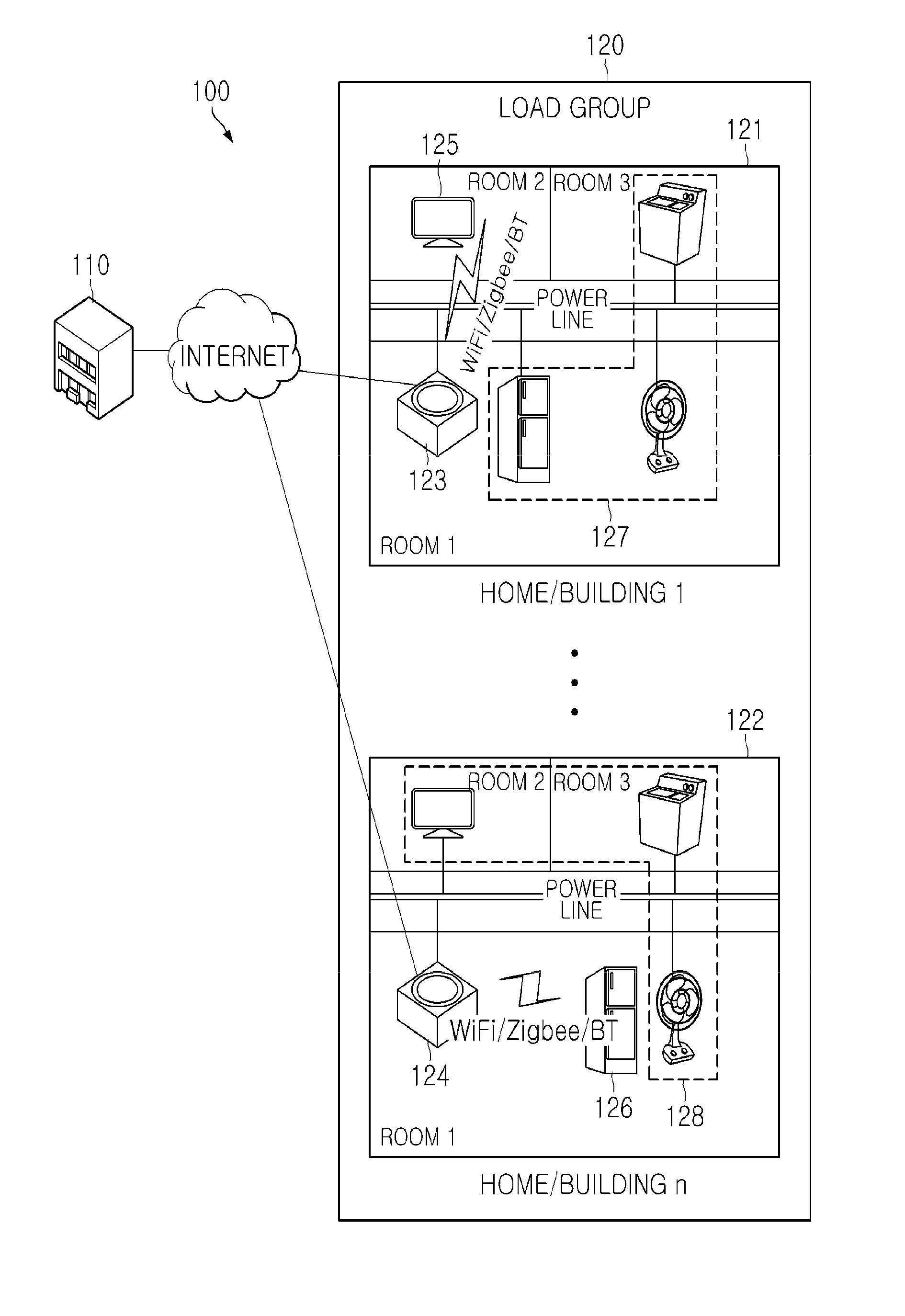
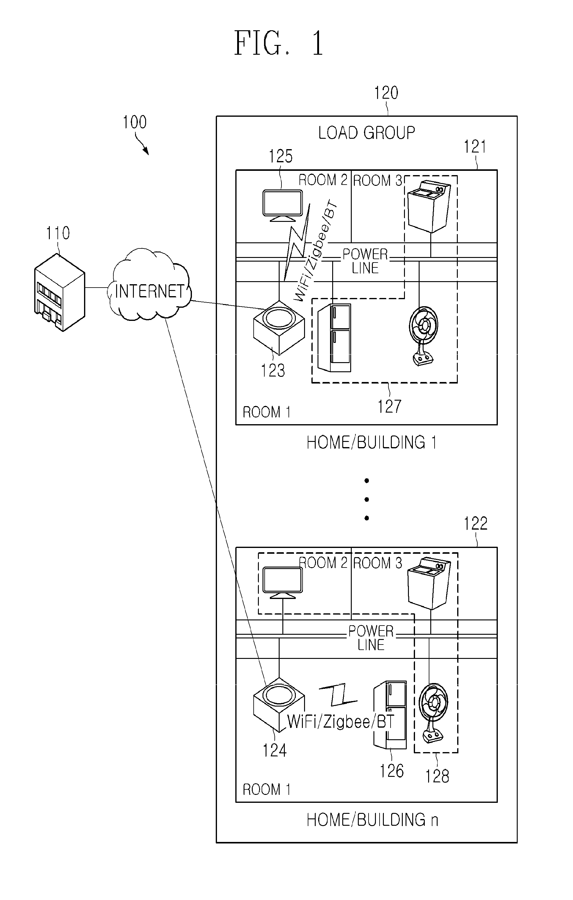
[0031]FIG. 1 is a view illustrating an exemplary power control system of an electrical device using a method of controlling maximum power use time according to an exemplary embodiment.

[0032]Referring to FIG. 1, a power control system 100 according to an exemplary embodiment includes a maximum demand power controller 110 and a load group 120 comprising a plurality of electric...


PUM


Abstract

A power control method includes: receiving a plurality of power use request information associated with a plurality of electrical devices, calculating a power consumption of the plurality of the electrical devices and an average value of the power consumption in a predetermined time period, based on the plurality of the power use request information, comparing the average value and the calculated power consumption in the predetermined time period to determine at least one scheduling interval in which the calculated power consumption is greater than the average value, and performing a scheduling in which a maximum power use time of at least one electrical device included in the at least one determined scheduling interval is moved to another interval The power use request information may be one from among time information and power consumption information corresponding to the operation of each of the plurality of the electrical devices.

Description

CROSS-REFERENCE TO RELATED APPLICATIONS[0001]This application claims priority from Korean Patent Application No. 10-2011-0133493, filed on Dec. 13, 2011, in the Korean Intellectual Property Office, the disclosure of which is incorporated herein by reference in its entirety.BACKGROUND[0002]1. Field[0003]Exemplary embodiments broadly relate to a method and a system for power control of an electrical device, and more particularly, to a method and a system for power control of an electrical device based on a control algorithm that controls the maximum power usage time.[0004]2. Description of the Related Art[0005]Smart grid is a next generation power network that combines IT technology with an existing power network and enables power providers and consumers to exchange two-way real-time information to maximize energy efficiency and to effectively manage power supply. The smart grid is being developed for a purpose of decreasing energy waste by increasing energy efficiency and for a purpo...

Claims


Application Information

Patent Timeline
IPC IPC(8): G06F1/26
CPCG06Q50/06H02J2003/143H02J3/14Y04S20/242Y02B70/3266Y04S20/222Y02B70/3225H02J2310/14Y02B70/30
Inventor BAE, YOUNG-HOJOO, WEON-YONG
Owner KT CORP
Learn More