Control apparatus for vehicle
a technology for controlling apparatus and vehicle, which is applied in the direction of hybrid vehicles, instruments, analogue processes for specific applications, etc., can solve the problems of reducing the driving force of the vehicle and affecting the drivability of the vehicle, and achieve the effect of suitably restrainting the drivability deterioration
- Summary
- Abstract
- Description
- Claims
- Application Information
AI Technical Summary
Benefits of technology
Problems solved by technology
Method used
Image
Examples
first embodiment
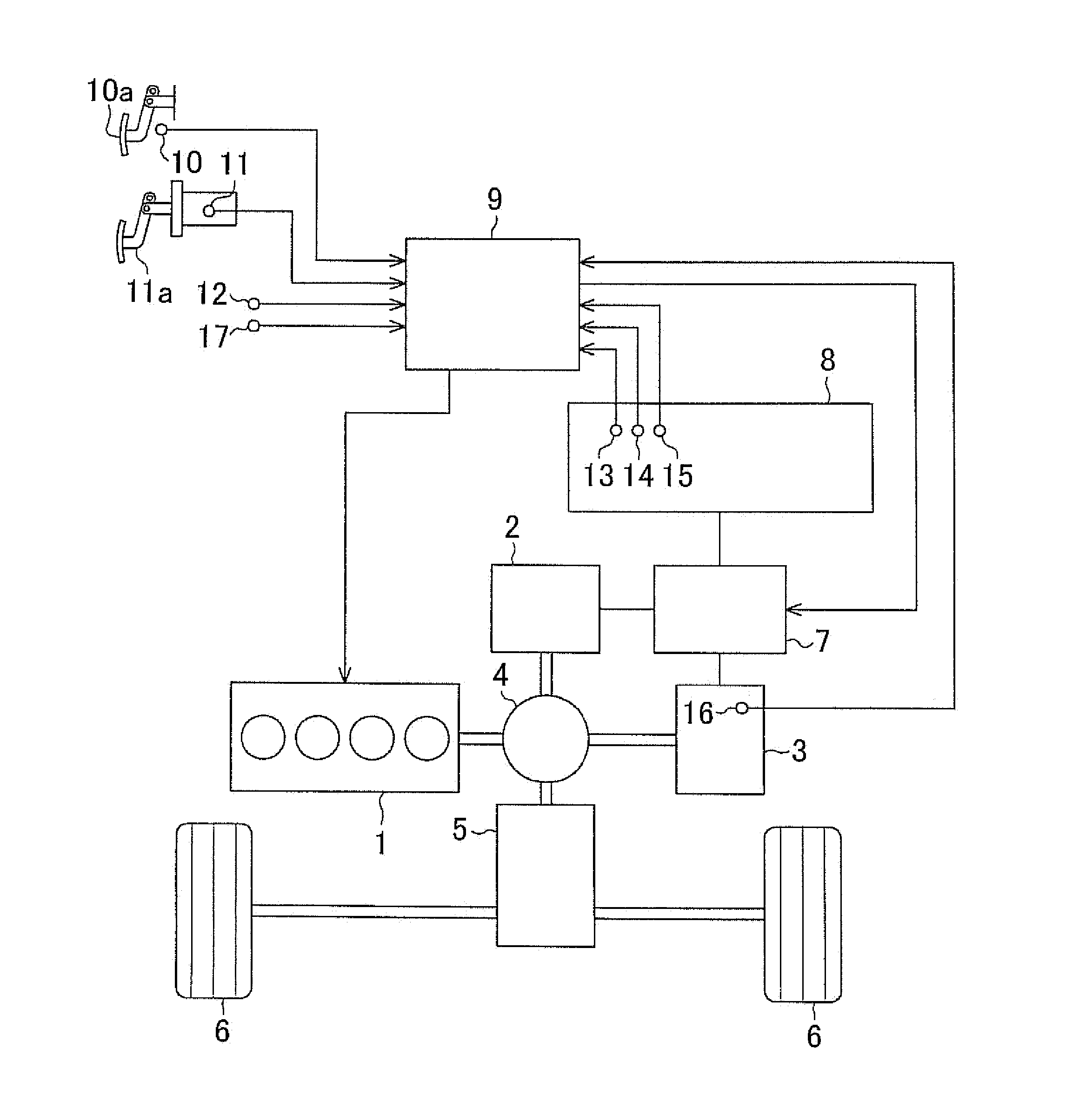
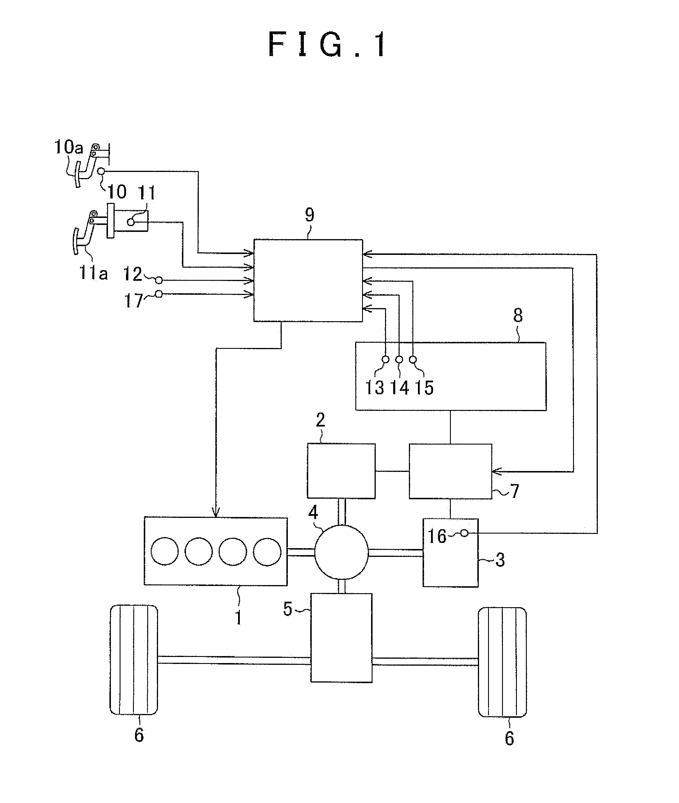
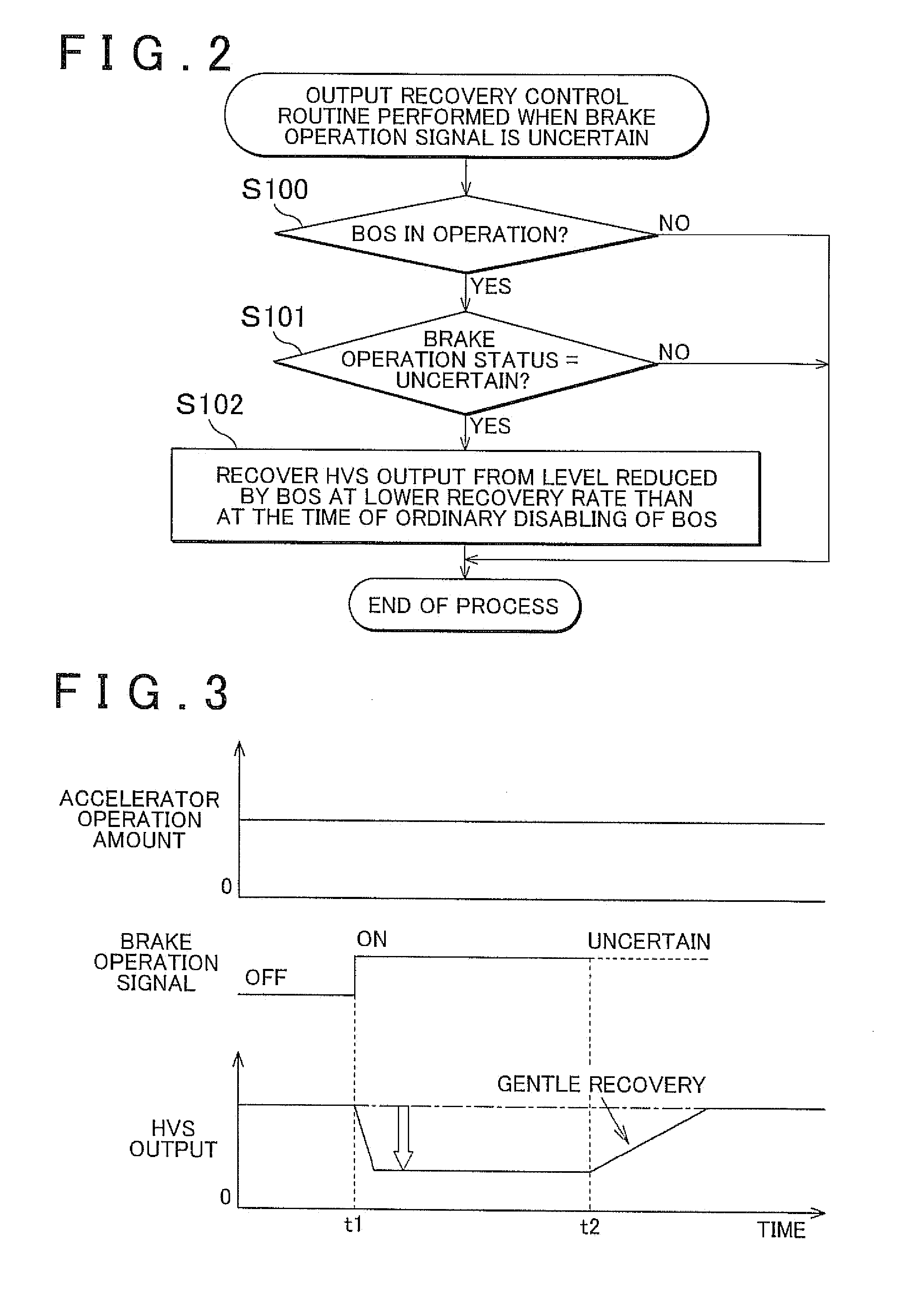
[0018]A first embodiment of the control apparatus for a vehicle of the invention will be described in detail hereinafter with reference to FIGS. 1 to 3.
[0019]Firstly, with reference to FIG. 1, a configuration of a hybrid system of a hybrid vehicle to which the control apparatus of this embodiment is applied will be described. This hybrid system includes an engine I that is a heat engine, and two motor-generators. In the following description, of the two motor-generators, one that is used mainly for electricity generation is referred to as the generator 2, and the other one, which is used mainly for producing drive force, is referred to as the electric motor 3.
[0020]The engine 1, the generator 2 and the electric motor 3 are connected to a power distribution mechanism 4 that includes a planetary gear mechanism. The power distribution mechanism 4 is connected to driving wheels 6 via a speed reducer mechanism 5. The power distribution mechanism 4 splits the motive power of the engine 1 ...
second embodiment
[0047]Next, a second embodiment of the control apparatus for a vehicle of the invention will be described in detail with reference to FIGS. 4 and 5 as well. With regard to this embodiment of the invention and also a third embodiment described below, components common to those of the foregoing embodiment are denoted by the same reference characters, and detailed descriptions thereof will be omitted.
[0048]In the first embodiment, if the brake operation signal becomes uncertain during operation of the BOS, the HVS output is recovered at that time point. Since the recovery of the HVS output at this time is conducted irrespective of the intention of the driver, the recovery may sometimes makes the driver feel uncomfortable.
[0049]Meanwhile, if during operation of the BOS the driver increases the amount of depression of the accelerator pedal 10a, it can be estimated that the driver intends to re-accelerate the vehicle. Therefore, in this embodiment, if the brake operation signal becomes un...
third embodiment
[0058]Next, a third embodiment of the control apparatus for a vehicle of the invention will be described in detail with reference to FIGS. 6 and 7 as well.
[0059]In the second embodiment, if the brake operation signal becomes uncertain during operation of the BOS, the recovery of the HVS output is carried out by estimating the driver's intention to re-accelerate the vehicle from increase in the accelerator operation amount. In this case, it is possible to re-accelerate the hybrid vehicle according to the demand of the driver. However, since increase of the accelerator operation amount and discontinuation of brake operation are not always simultaneously performed, the recovery of the HVS output may sometimes be conducted at a timing different from the timing of the recovery performed when the brake operation signal is not uncertain.
[0060]Meanwhile, in some cases, the status of operation of the brake pedal 11a can be determined on the basis of another signal than the brake operation si...
PUM
 Abstract
Description
Claims
Application Information
 - R&D
- Intellectual Property
- Life Sciences
- Materials
- Tech Scout
- Unparalleled Data Quality
- Higher Quality Content
- 60% Fewer Hallucinations
Browse by: Latest US Patents, China's latest patents, Technical Efficacy Thesaurus, Application Domain, Technology Topic, Popular Technical Reports.
© 2025 PatSnap. All rights reserved.Legal|Privacy policy|Modern Slavery Act Transparency Statement|Sitemap|About US| Contact US: help@patsnap.com


