Modular electric disc cutterbar and controller

a technology of electric disc cutter and controller, applied in the field of rotary disc cutter, can solve the problems of increased manufacturing cost, over-designed drivetrain parts capable of handling loads far, and increased weight of cutterbar

Active Publication Date: 2013-06-20
CNH IND CANADA
View PDF2 Cites 26 Cited by
  • Summary
  • Abstract
  • Description
  • Claims
  • Application Information

AI Technical Summary

Benefits of technology

[0006]Accordingly, the present invention, in any of the embodiments described herein, may provide one or more of the following advantages:
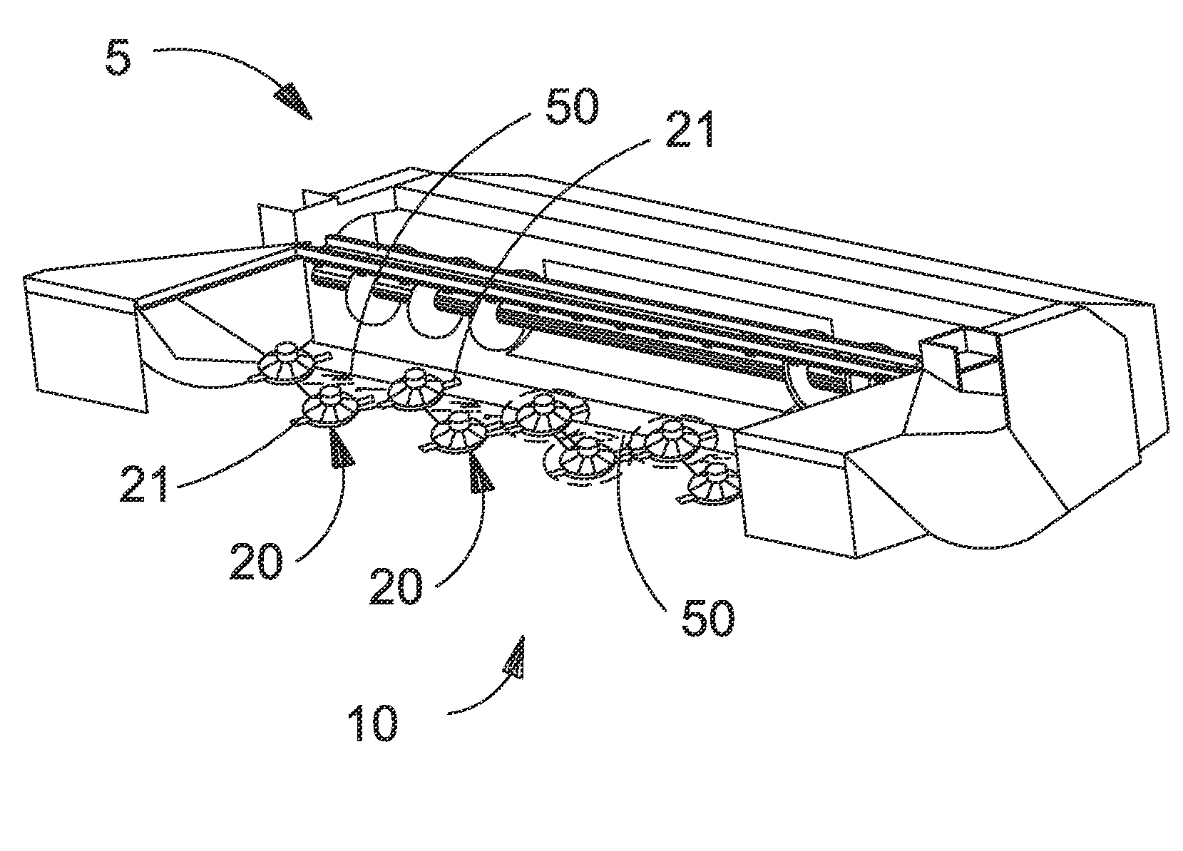
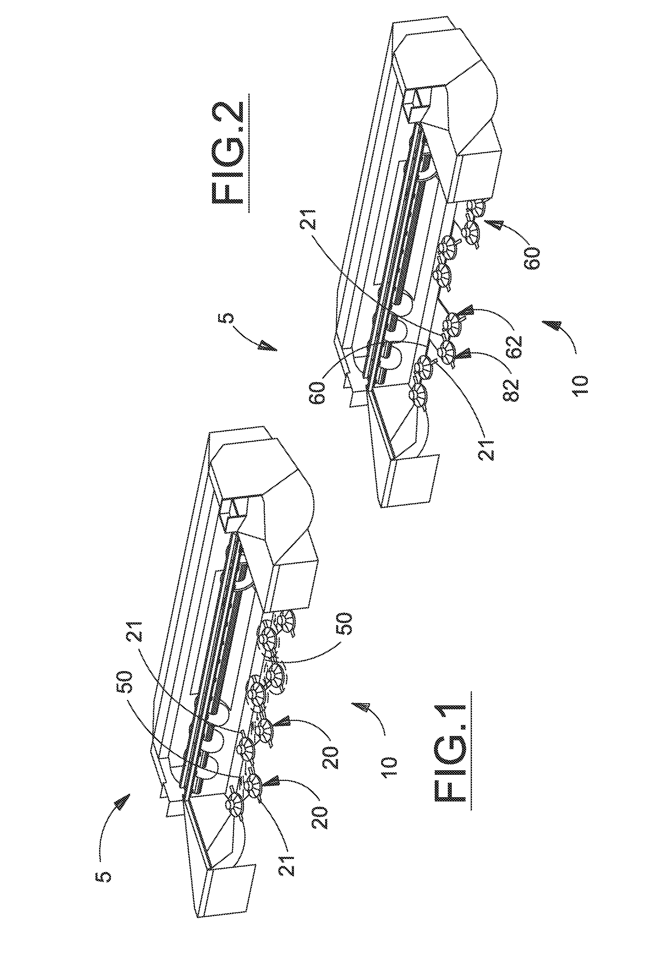
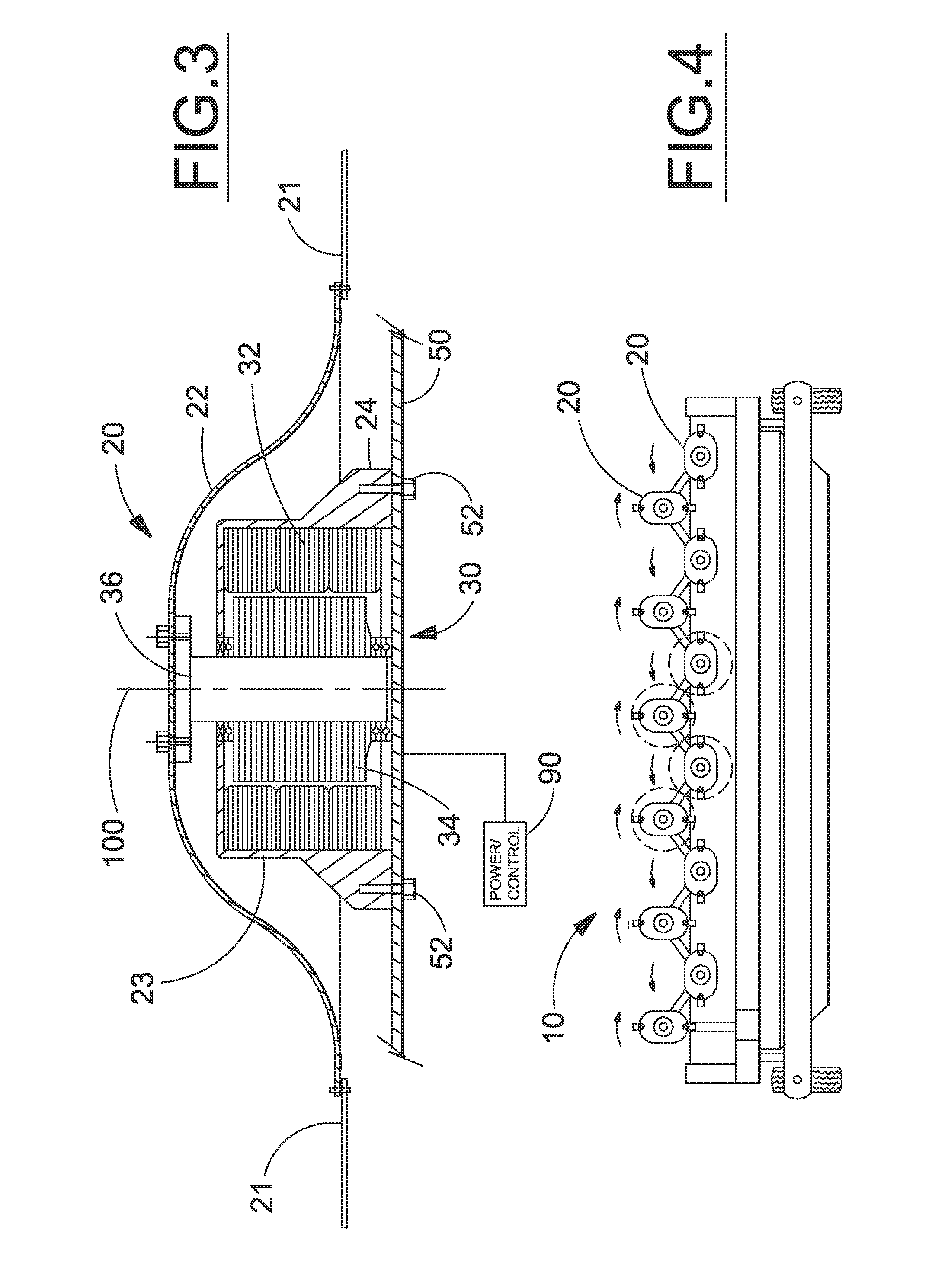
[0007]It is an object of the present invention to provide an electrically driven cutterhead module for a header that allows cutterheads to be individually powered or powered in pairs thereby eliminating the need for a cutterbar mechanical drivetrain to transfer drive power across the cutterbar width.
[0008]It is a further object of the present invention to provide an electric motor driven cutterhead for a modular disc cutterbar that reduces cutterbar weight compared to a mechanically driven modular cutterbar to provide greater flexibility in repositionable cutterbar designs, including articulated cutterbars enabling large cutting widths capable of easy repositioning for transport.

Problems solved by technology

The power transmission requirement and shock loadings resulting from cutter impact with rocks and other obstructions generally result in over-designed drivetrain parts capable of handling loads far greater than the loadings on an isolated rotary disc cutterhead.
The additional strength in a modular cutterhead results in greater weight for the cutterbar and greater manufacturing costs.
However, replacing a single damaged cutterhead module is not an insignificant task requiring significant disassembly of the cutter bar in order to remove a damaged cutterhead from the cutterbar driveline because of intermediate drive shafts disposed between adjacent modules to transfer power laterally along the cutterbar.

Method used


Image

  • Modular electric disc cutterbar and controller
  • Modular electric disc cutterbar and controller
  • Modular electric disc cutterbar and controller

Examples


Embodiment Construction

)

[0026]Many of the fastening, connection, processes and other means and components utilized in this invention are widely known and used in the field of the invention described, and their exact nature or type is not necessary for an understanding and use of the invention by a person skilled in the art, and they will not therefore be discussed in significant detail. Also, any reference herein to the terms “left” or “right” are used as a matter of mere convenience, and are determined by standing at the rear of the machine facing in its normal direction of travel. Likewise, “forward” and “rearward” are determined by the normal direction of travel. “Upward” and “downward” orientations are relative to the ground or operating surface as are any references to “horizontal” or “vertical” planes. Furthermore, the various components shown or described herein for any specific application of this invention can be varied or altered as anticipated by this invention and the practice of a specific ap...


PUM


Abstract

An electric motor-driven rotary disc cutter module for a cutterbar in an agricultural harvester. In one embodiment, each rotary disc module includes an electric motor driver. Individual cutterhead modules are staggered fore and aft along the cutterbar to provide continuous cutting across the lateral width of the cutterbar without requiring synchronized rotation of the cutterheads. Individual speed and / or rotational direction adjustment of each cutterhead enables optimized crop cutting performance and / or crop movement within the header. A control system may be included to monitor performance and manage individual operation of the cutterhead modules. In a second embodiment, a pair of cutterheads are powered by a single electric motor wherein rotational input for the second cutterhead is transferred by a simple geartrain. The pair of cutterheads is combined into a modular arrangement with the modules being staggered fore and aft on the cutterbar to provide a continuous lateral cutting swath.

Description

BACKGROUND OF THE INVENTION[0001]This invention relates generally to a machine for severing standing crops from the ground to initiate a harvesting process and, more particularly, to a rotary disc cutterbar having a preselected number of transversely oriented, electric motor powered rotatable discs with knives mounted thereon to sever standing crop by an impact action upon rotation of the discs.[0002]Typical disc cutterbars used in agriculture include an elongated housing containing a train of meshed idler and drive spur gears, or a main power shaft or series of power shafts coupled by respective bevel gear sets, for delivering power to respective drive shafts for modular cutterheads spaced along the length of the cutterbar. The cutterheads each comprise a cutting disc including diametrically opposed cutting blades (though configurations with three or more blades are known) and having a hub coupled to an upper end of a drive shaft, the lower end of the drive shaft carrying a spur ge...

Claims


Application Information

Patent Timeline
Patent Type & Authority Applications(United States)
IPC IPC(8): A01D34/78A01D34/73A01D34/66
CPCA01D34/78A01D34/008A01D34/665A01B73/00
Inventor ROBERGE, MARTIN J.
Owner CNH IND CANADA
Why Eureka
Try Eureka