Composite valve

a valve body and valve body technology, applied in the field of composite valves, can solve the problems of increasing the size increasing the electric power consumption, and increasing the cost of the whole valve, so as to improve the controllable flow rate, improve the flow rate control precision, and reduce the effect of pressure loss

Active Publication Date: 2013-06-20
FUJIKOKI CORP
View PDF7 Cites 5 Cited by
  • Summary
  • Abstract
  • Description
  • Claims
  • Application Information

AI Technical Summary

Benefits of technology

[0048]Since the composite valve in accordance with the present invention is provided with the pilot valve body which is independent from the second valve body, in addition to the first control valve for the large flow rate (the first valve body and the first valve port), and the second control valve for the small flow rate (the second valve body and the second valve port), and is structured such as to drive the pilot valve body so as to open and close by utilizing the elevating motion of the valve shaft which is provided with the second valve body, it is possible to set the dimension and the shape of the second control valve for the small flow rate (the second valve body and the second valve port) so as to be optimum for the small flow rate control, and it is possible to securely carry out the opening and closing of the first control valve for the large flow rate at a desired timing. Further, since the structure is made such as to circulate the refrigerant without passing through the narrow portion such as the sliding surface gap or the like as is different from the conventional one, at a time of controlling the small flow rate, it is possible to make the malfunction hard to be generated. As a result, it is possible to achieve both an improvement of the flow rate control precision in the small flow rate region, and an increase of the controllable flow rate (a reduction of the pressure loss), without causing an increase of a motion load, and an enlargement in size of the driving portion (the motor portion) and the valve main body.

Problems solved by technology

However, in the composite valve described in the Japanese Patent Application No. 2011-68451 mentioned above, there has been the following problem to be improved.
If the valve closing spring having the large spring load is used, it is necessary to use an electrically operated motor which generates the corresponding driving torque, in order to lift up the second valve body against the energizing force of the valve closing spring, thereby causing a cost increase, an enlargement in size of a whole valve, an increase of an electric power consumption and the like.
Further, if the bore diameter of the second valve port is constrained as mentioned above, it becomes hard to achieve both the improvement of the flow rate control precision in the small flow rate region and the improvement of the controllable flow rate (the reduction of the pressure loss).

Method used


Image

  • Composite valve
  • Composite valve
  • Composite valve

Examples


Embodiment Construction

[0055]A description will be given below of an embodiment in accordance with the present invention with reference to the accompanying drawings.

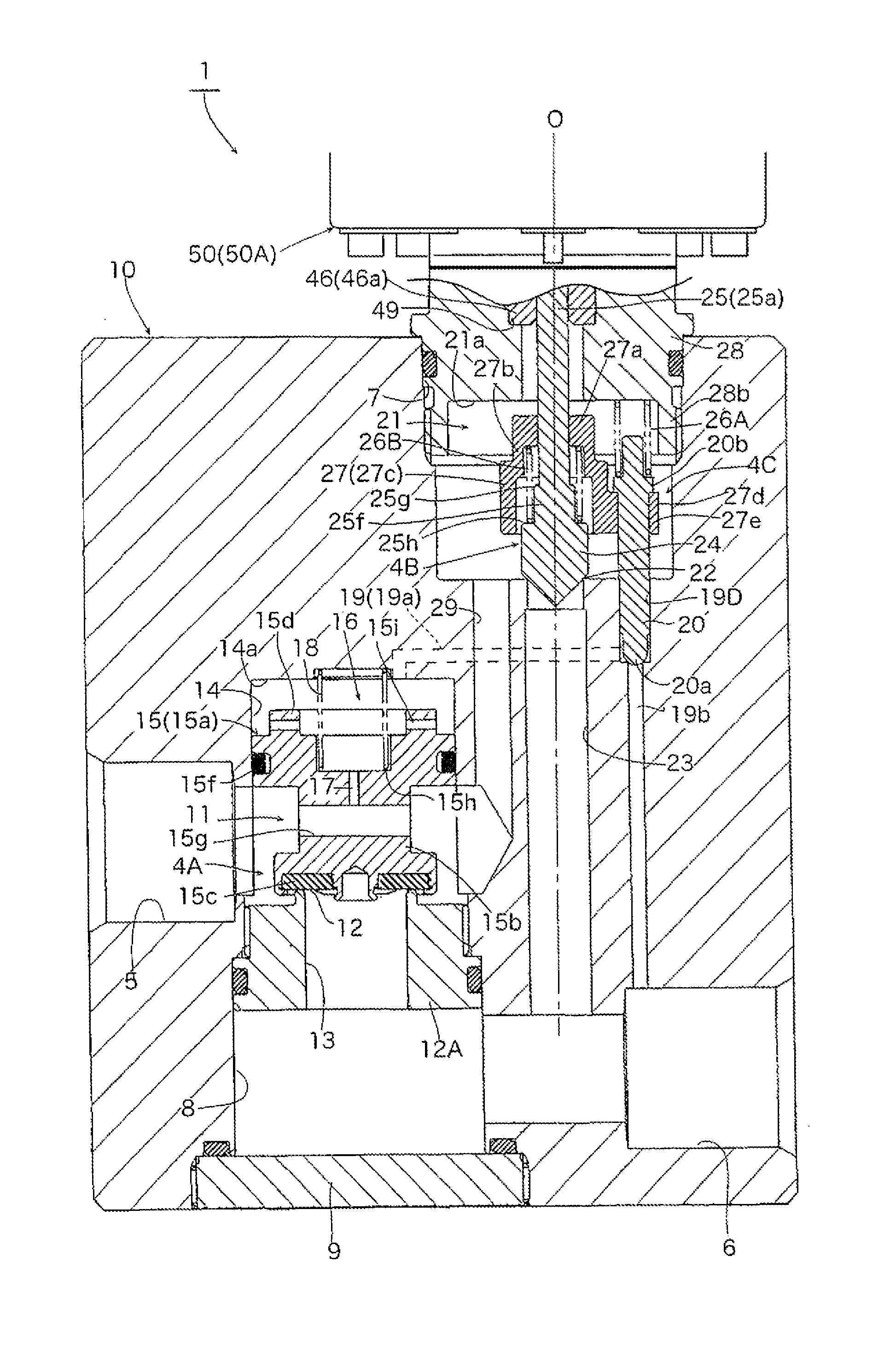
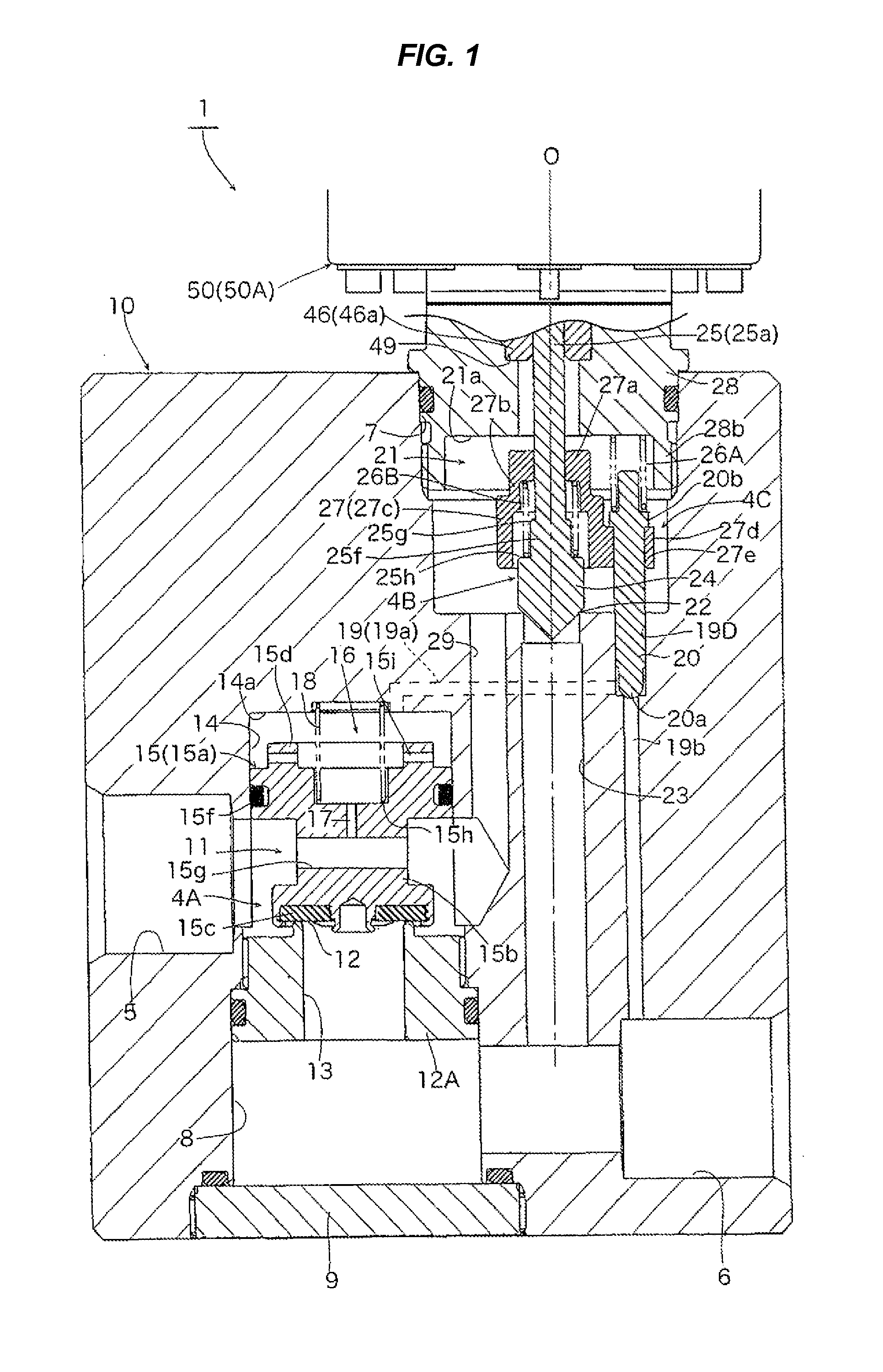
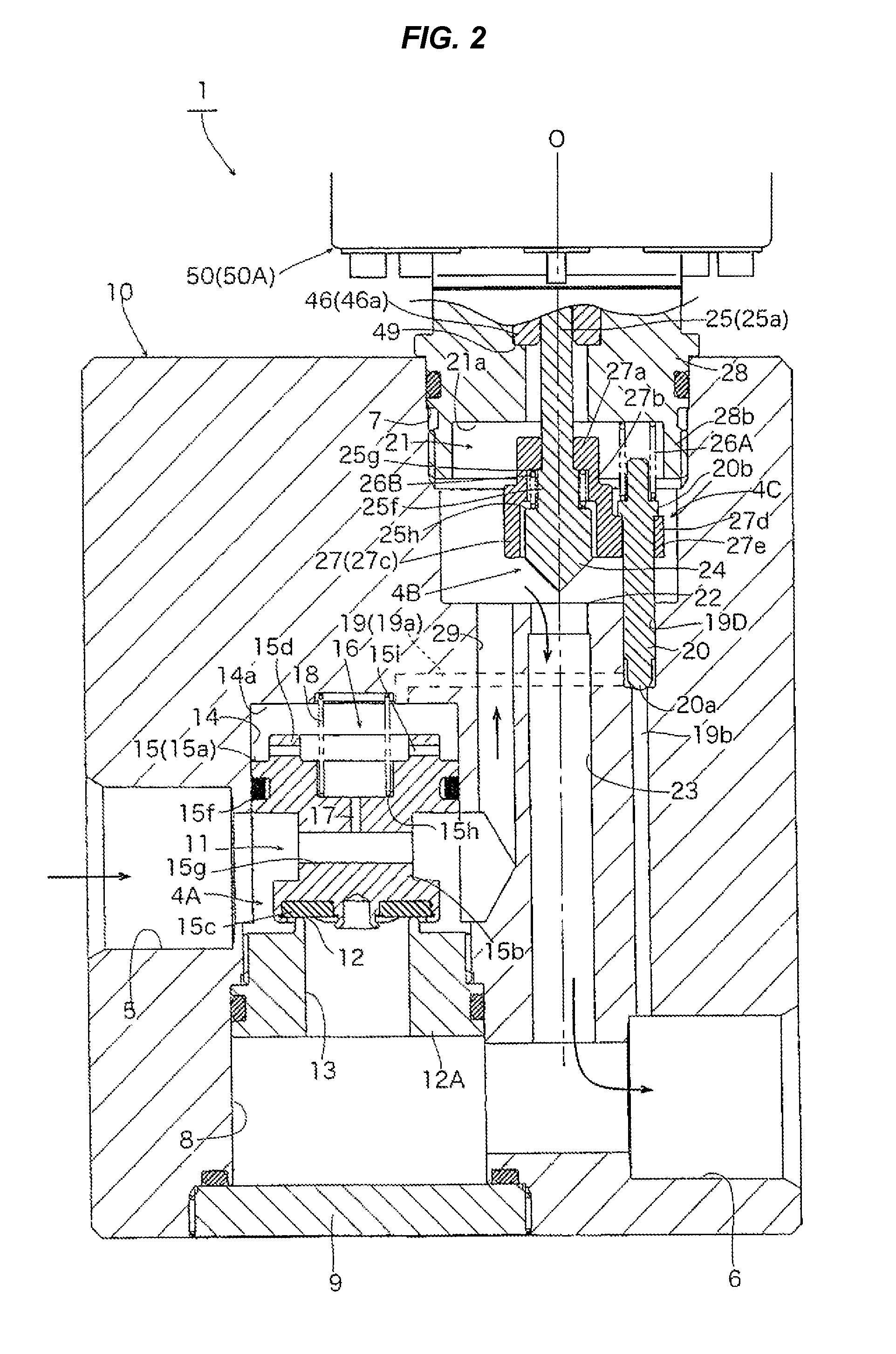
[0056]FIGS. 1 to 3 are enlarged cross sectional views of a substantial part and show an embodiment of a composite valve in accordance with the present invention, in which the respective drawings show different motion states. Since a stepping motor (an actuator) 50 portion of a composite valve 1 in accordance with the illustrated embodiment is approximately the same as that of the conventional electrically operated valve 1′ shown in FIG. 4, the portion is omitted.

[0057]The composite valve 1 in accordance with the illustrated first embodiment is provided with a rectangular parallelepiped valve main body 10 which is larger than the valve main body 40 (FIG. 4) of the electrically operated valve 1′ in the conventional example, a pilot type first control valve 4A for a larger flow rate (a first valve body 15 and a first valve port 13), a second cont...


PUM


Abstract

A composite valve has a communication path, a second valve port and a pilot passage. First and second valve bodies are arranged to be moved up and down in the same direction, and are away from each other only at a predetermined distance. In the case that a lift amount of the second valve body for a small flow rate control is equal to or less than a predetermined amount, said pilot passage and a first valve port are respectively closed by a pilot valve body and the first valve body, thereby taking a small flow rate control state. In the case that the lift amount of said second valve body goes beyond said predetermined amount, said pilot valve body is moved up by the upward movement of a valve shaft to open said pilot passage, thereby taking a large flow rate control state.

Description

BACKGROUND OF THE INVENTION[0001]1. Field of the Invention[0002]The present invention relates to a composite valve which is preferably used in a heat pump type cooling and heating system or the like, and more particularly to a composite valve which is provided with a pilot type large flow rate control valve and a small flow rate control valve.[0003]2. Description of the Conventional Art[0004]As a heat pump type cooling and heating system, there has been conventionally known a structure which is provided with a compressor, a condenser, an evaporator, an expansion valve and a four-way valve for converting (inverting) a refrigerant flow path.[0005]On the other hand, as a heat pump type cooling and heating system for a vehicle (for example, for an electric vehicle), there has been proposed a system which does not invert a flow of a refrigerant and is provided independently with an expansion valve for cooling and an expansion valve for heating, for example, as shown in FIG. 1 of Japanese...

Claims


Application Information

Patent Timeline
Patent Type & Authority Applications(United States)
IPC IPC(8): F16K31/12
CPCF25B41/062F25B2341/065Y02B30/72F16K31/12F25B2341/0671Y10T137/7758Y02B30/70F25B41/34F25B2341/067F25B41/35F16K31/04F16K31/406
Inventor ARAI, YUSUKE
Owner FUJIKOKI CORP
Why Eureka
Try Eureka