Method for internally generating electric energy in electric vehicles

Inactive Publication Date: 2013-06-20
LIM JAE HYUN
View PDF2 Cites 7 Cited by
  • Summary
  • Abstract
  • Description
  • Claims
  • Application Information

AI Technical Summary

Benefits of technology

[0005]The key concept of this method is that the mechanical rotational energy from the axel shaft is converted to electric energy while the vehicle is in motion,

Problems solved by technology

However, there are many limitations that must be addressed to make HEVs and EVs more efficient.
One i

Method used


Image

  • Method for internally generating electric energy in electric vehicles
  • Method for internally generating electric energy in electric vehicles
  • Method for internally generating electric energy in electric vehicles

Examples


Example

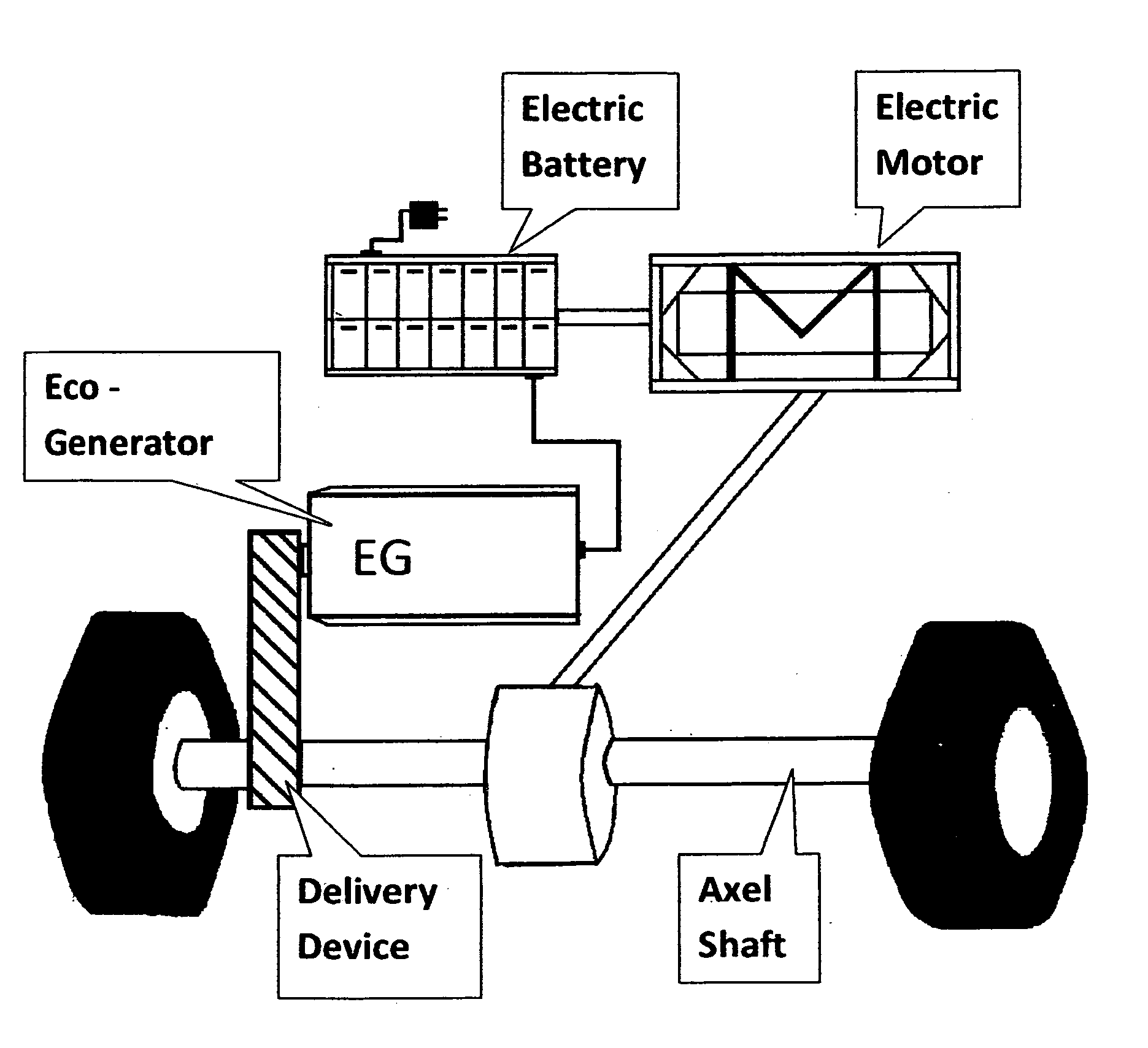
[0010]The vehicle's electric battery supplies power to rotate the axel shafts which all work to move the vehicle by rotating the wheels.

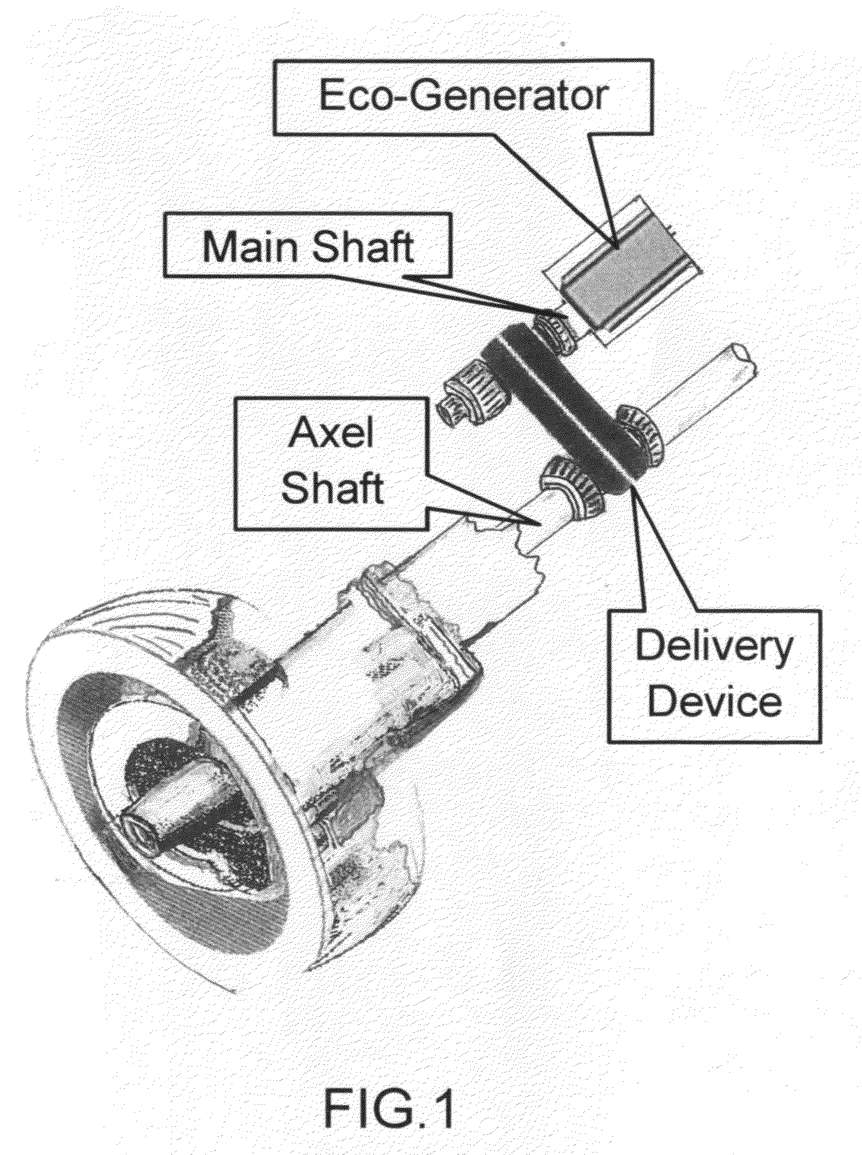
[0011]The delivery device in FIG. 1 transfers the rotating axel shaft energy to the main shaft of the Eco-Generator. This delivery device can be composed of a belt, chain, gears, etc.

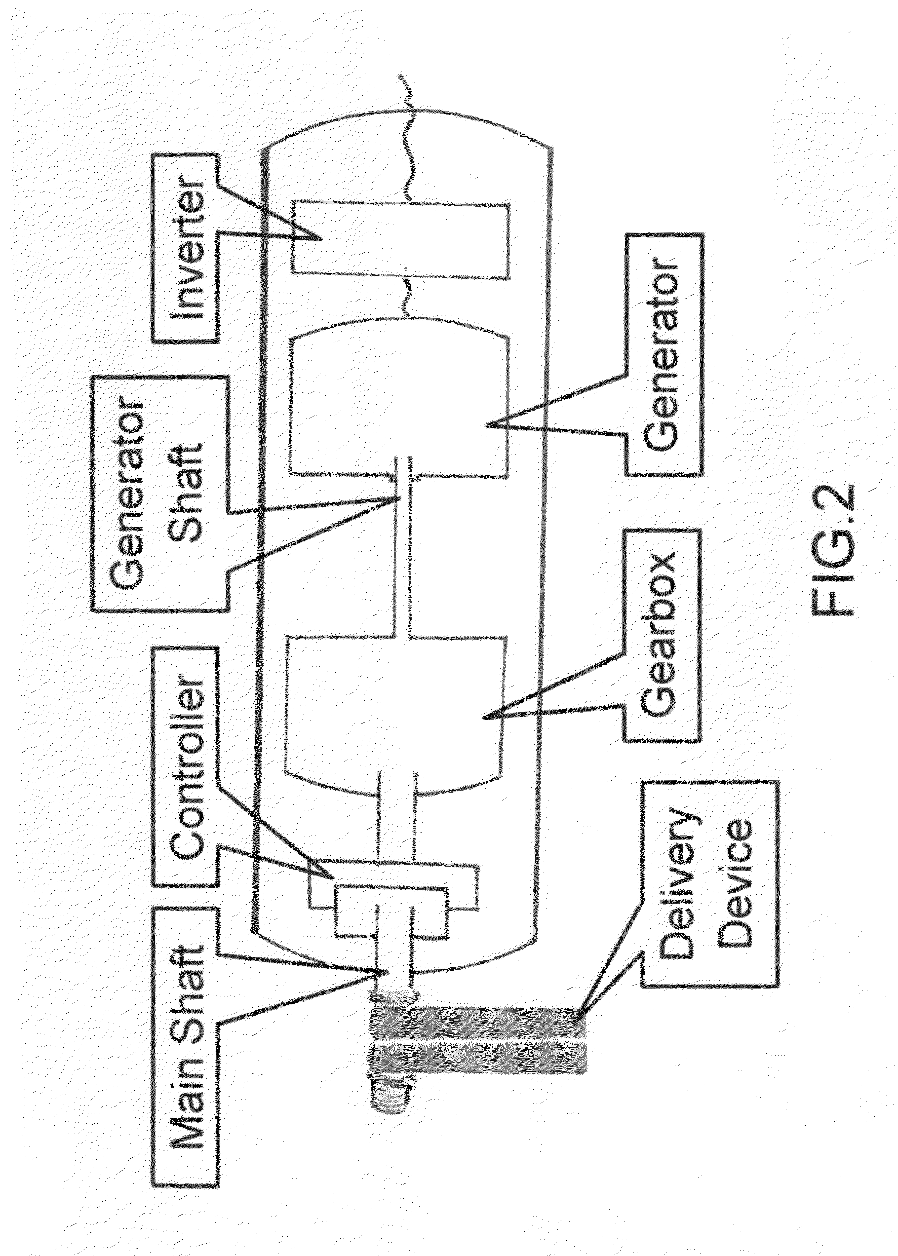
[0012]The Eco-Generator as shown in FIG. 2 consists of a controller, a gearbox, a generator, and an inverter. The controller consists of a brake system and a sensor. The brake system manages the rotational speed of the main shaft, which depends on the operator's driving patterns. The sensor regulates the temperature of the Eco-Generator by adjusting the brake system to control the rotational speed of the main shaft. The gearbox transfers the rotational velocity of the main shaft to the generator shaft which would result in a higher rotational velocity. The generator converts the mechanical rotational energy of the generator shaft to electrical energy. Then, the electric...


PUM


Abstract

Disclosed is a method to create an extra electric energy source to power electric batteries while the electric vehicle is in motion. This electric energy source is generated from a separate internally installed component (a specially designed “Eco-Generator”). This component converts the axel shaft rotational energy through a delivery device.

Description

BACKGROUND OF THE INVENTION[0001]The hybrid electric vehicle (HEV) and the electric vehicle (EV) are currently experiencing a growth in development and demand due to the growing lack of fossil fuels and due to carbon dioxide emissions from exhaust in conventional fuel cars. Therefore, in many countries and local governments, there are many incentives and promotions granted to develop HEVs and EVs in an effort to make them more attractive to the public market.[0002]However, there are many limitations that must be addressed to make HEVs and EVs more efficient. One important limitation is the insufficient capacity of the electric batteries used in electric vehicles. Because there are currently not many electric charging infrastructures (charging stations), there is a great interest to increase the capacity of electric vehicle batteries instead. Increasing its electric capacity would offer significant performance benefits in mileage per complete plug-in charge and make electric vehicles...

Claims


Application Information

Patent Timeline
IPC IPC(8): B60L11/18H02K53/00
CPCY02T10/641B60L7/16B60K25/00H02K53/00Y02T10/64
Inventor LIM, JAE HYUN
Owner LIM JAE HYUN
Why Eureka
Try Eureka