
Systems and Methods for Predicting Power System Instability

a technology of power system and system, applied in the field of systems and methods for predicting power system instability, can solve problems such as voltage regulation, stability, power system outages, and power system integration into existing power systems

Active Publication Date: 2013-06-20
GENERAL ELECTRIC CO
View PDF5 Cites 19 Cited by
  • Summary
  • Abstract
  • Description
  • Claims
  • Application Information

AI Technical Summary

Benefits of technology

The invention provides a system and method for predicting instability in a power system, specifically the potential for a drop in voltage or power flow. This is accomplished by measuring current and voltage on busses and calculating changes in reactive power loss and real power flow. By doing so, the system can alert users to potential instability and take necessary measures to prevent damage or malfunction.

Problems solved by technology

A frequently occurring situation in an electric power system is the need to transmit more power over the system than it was originally designed for.
Furthermore, with increased distributed generation, the integration of distributed generators into existing power systems presents technical challenges such as voltage regulation, stability, power quality problems.
Typically, electrical power systems are monitored and controlled to provide continuous and reliable service; however, power systems outages can still occur and are often associated with voltage instabilities.
Voltage collapse in certain areas of a power network can lead to blackouts, which can result in revenue loss for both customers and the utilities.
One cause for voltage collapse can be attributed to lack of reactive power resources in the system, or the improper application thereof.

Method used


Image

  • Systems and Methods for Predicting Power System Instability
  • Systems and Methods for Predicting Power System Instability
  • Systems and Methods for Predicting Power System Instability

Examples


Embodiment Construction

[0014]Embodiments of the invention will be described more fully hereinafter with reference to the accompanying drawings, in which embodiments of the invention are shown. This invention may, however, be embodied in many different forms and should not be construed as limited to the embodiments set forth herein; rather, these embodiments are provided so that this disclosure will be thorough and complete, and will fully convey the scope of the invention to those skilled in the art.

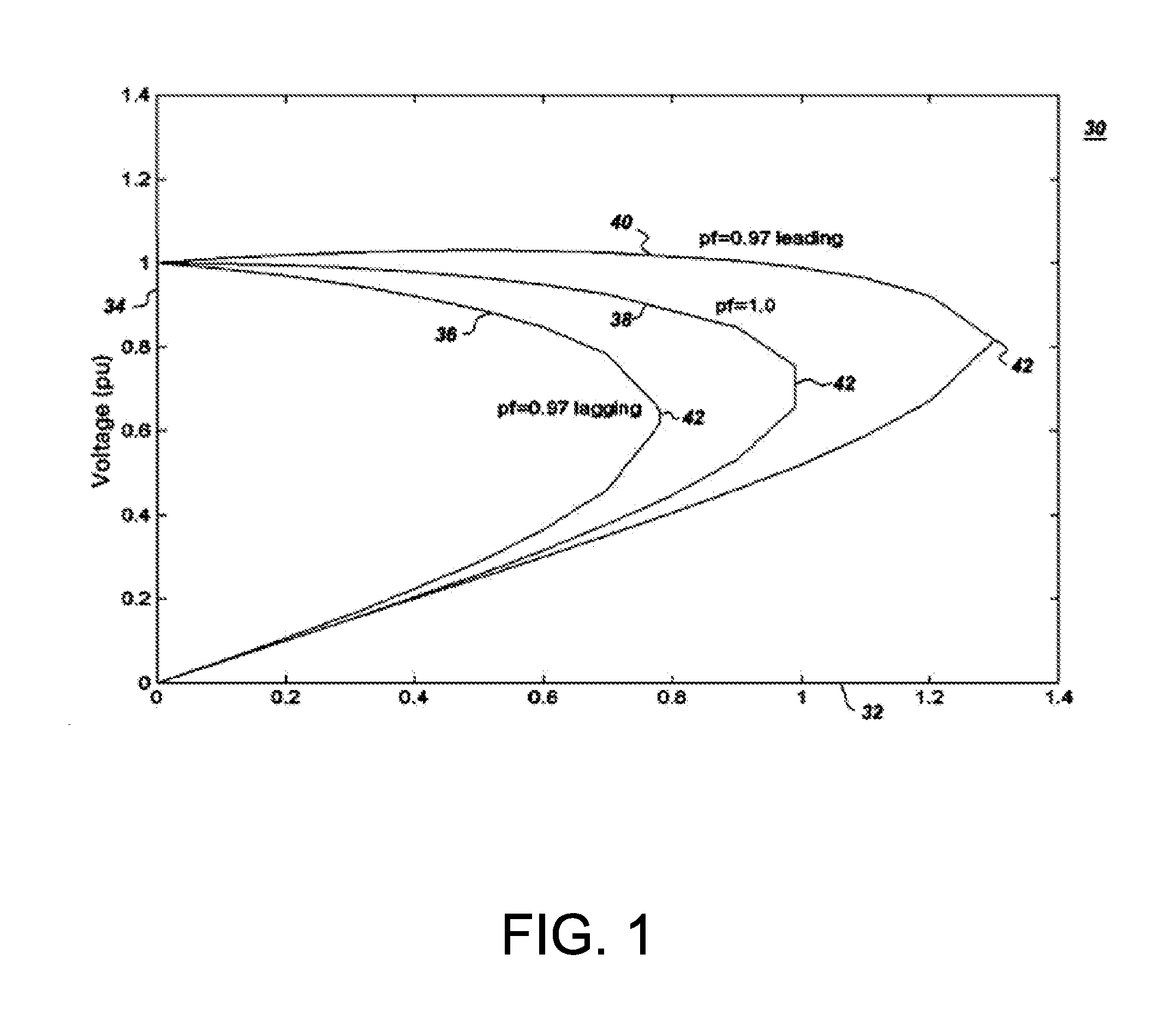
[0015]FIG. 1 shows a graphical representation 30 of a power-voltage (P-V) curve of an electrical power system. A horizontal axis 32 represents the active power P in terms of per unit (pu) and a vertical axis 34 represents a line voltage in pu. Three plots 36, 38, 40 represent P-V curves for three different power factors (i.e., 0.97 lagging, unity, and 0.97 leading respectively). A nose point 42 on each of the curves represents a voltage stability limit at the respective power factor. As will be appreciated by ...


PUM


Abstract

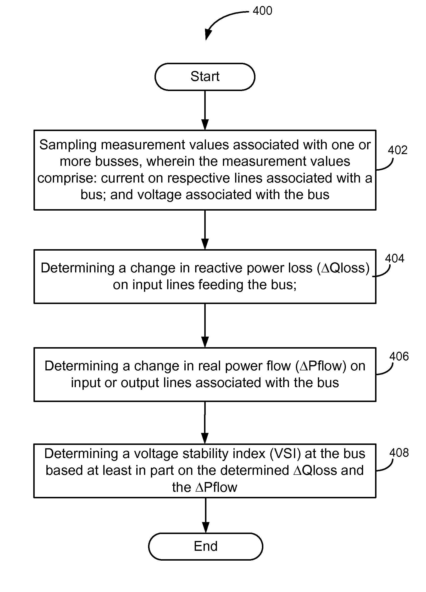
Certain embodiments of the invention may include systems and methods for predicting power system instability. According to an example embodiment of the invention, a method is provided for predicting voltage collapse or instability in a power system. The method can include sampling measurement values associated with one or more busses, wherein the measurement values include current on respective lines associated with a bus; and voltage associated with the bus. The method can further include determining a change in reactive power loss (ΔQloss) on input lines feeding the bus; determining a change in real power flow (ΔPflow) on input or output lines associated with the bus; and determining a voltage stability index (VSI) at the bus based at least in part on the determined ΔQloss and the ΔPflow.

Description

FIELD OF THE INVENTION[0001]This invention generally relates to electrical power systems, and in particular, to systems and methods for predicting power system instability.BACKGROUND OF THE INVENTION[0002]The basic structure of an electric power system includes various hardware elements such as generators, transformers, power lines, and real-time monitoring equipment. Certain software enables monitoring and control of the electric power systems with computer systems. The software can include power flow analysis software, fault detection software, and restoration software for generation, transmission, and distribution of electricity.[0003]A frequently occurring situation in an electric power system is the need to transmit more power over the system than it was originally designed for. In cases where there is a need to transmit more power, and building new transmission lines is prohibitive due to cost, right-of-way, or environmental constraints, increased utilization of existing trans...

Claims


Application Information

Patent Timeline
Patent Type & Authority Applications(United States)
IPC IPC(8): G01R11/63
CPCH02J3/00H02J3/24G01R11/63H02J3/242Y04S10/22Y02E40/70Y02E60/00
Inventor GADIRAJU, KASI VISWANADHA RAJUKOLWALKAR, AMOLGURRALA, GURUNATH
Owner GENERAL ELECTRIC CO
Learn More