Method for Detecting a Working Area and Device Therefor

Active Publication Date: 2013-06-20
ROBERT BOSCH GMBH
View PDF1 Cites 26 Cited by
  • Summary
  • Abstract
  • Description
  • Claims
  • Application Information

AI Technical Summary

Benefits of technology

[0028]The above method has the advantage that the reconstructed boundary signal can be correlated with a reference signal with little computational complexity in a mobile device, with the result that it is possible to detect whether the mobile device is inside or outside an area defined by a boundary conductor. This applies, in particular, as early as when the device is switched on, without the need for previous learning.
[0029]Pseudo-random signals which have very favorable frequency spectrum properties are preferably used as the transmission signal, thus resulting in a very high degree of reliability of the method even under interference-intensive environmental conditions. Furthermore, these signals can be generated in a simple manner, for example with the aid of a shift register and logic gates, for example an exclusive-OR gate.
[0030]In particular, another advantage is that there is no need to learn what area the de

Problems solved by technology

However, a disadvantage of these systems is that it is not possible to detect on what side of the current-carrying boundary conductor the corresponding detection coil is located, that is to say whether the working device is inside or outside the defined working area.
In particular, with this method, it is not possible to determine whether the working device is inside or outside the working area when the m

Method used


Image

  • Method for Detecting a Working Area and Device Therefor
  • Method for Detecting a Working Area and Device Therefor
  • Method for Detecting a Working Area and Device Therefor

Examples


Embodiment Construction

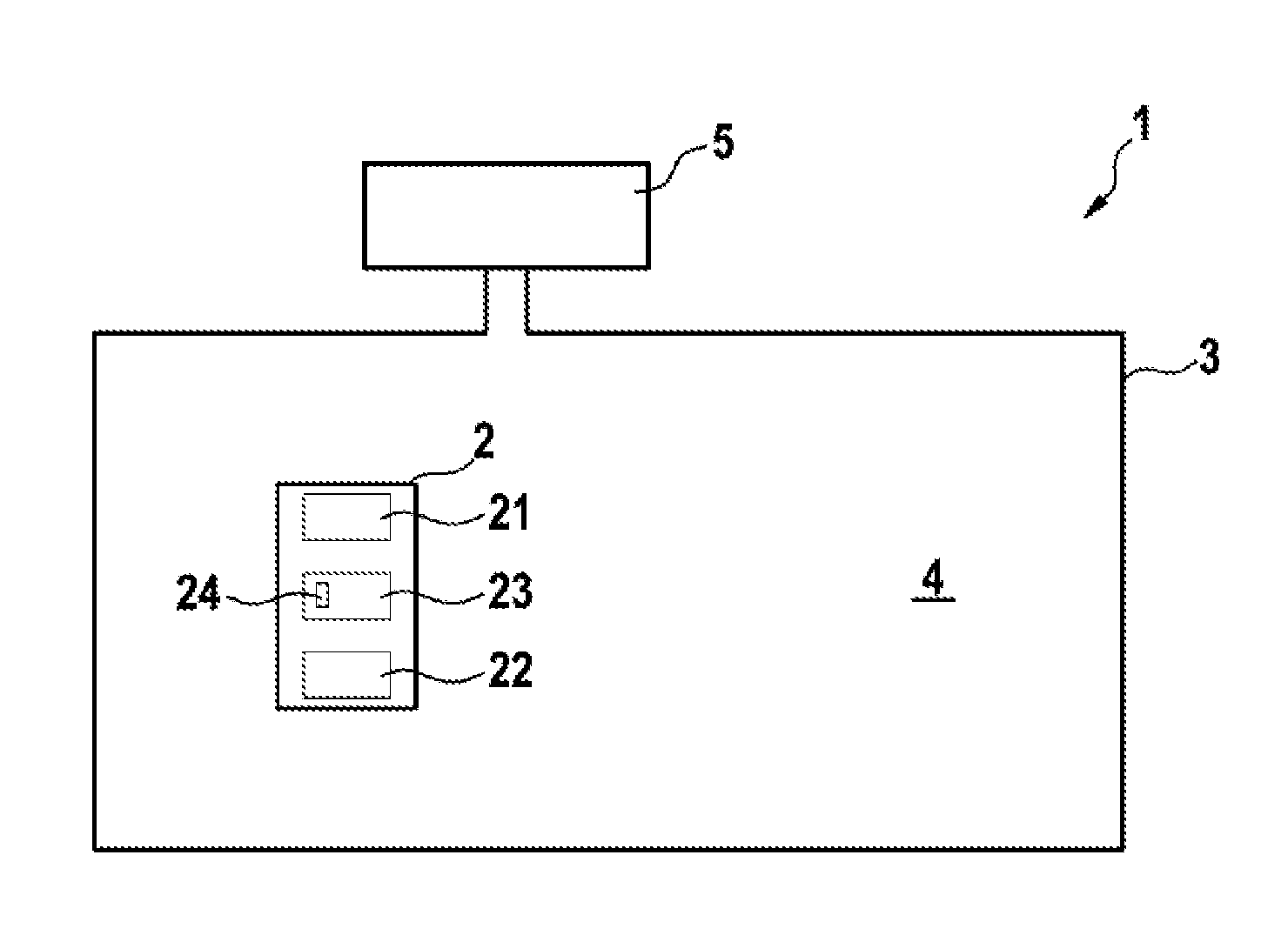
[0060]The invention generally relates to devices which can detect whether they are inside or outside a defined area. In particular, these devices may be mobile working devices or monitoring devices.

[0061]Mobile working devices may be, for example, automatic or semi-automatic working devices for ground treatment and may undertake tasks, for example lawn mowing, scarifying, aerating, collecting leaves, watering the garden, fertilizing the garden / lawn, clearing snow and, in the domestic sector, vacuuming, wiping floors, washing floors, polishing floors and the like. In the industrial sector, the ground treatment tasks may include preparing icy surfaces and vacuuming / wiping / washing / polishing floors in halls and the like.

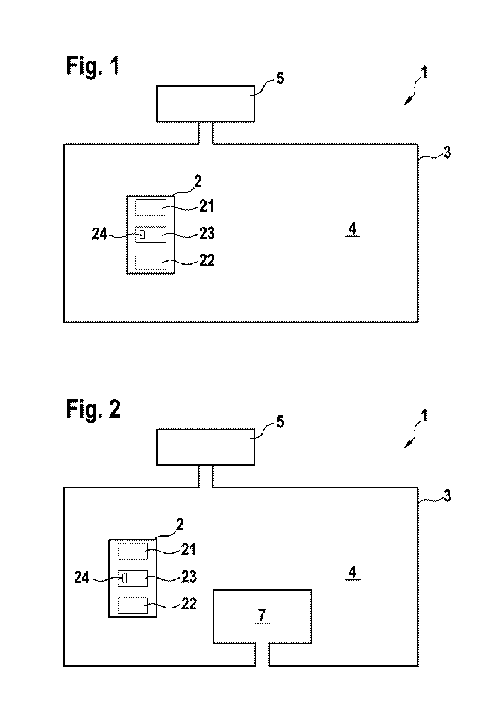
[0062]In alternative embodiments, the device may also be in the form of a monitoring device in order to monitor whether a person, an animal or an item moves from a predefined monitoring area, with the result that said device is suitable, for example, for applications wit...


PUM


Abstract

A method for detecting a position with respect to a mobile working machine includes providing a current signal in a boundary conductor, which surrounds the defined area, in accordance with a boundary signal that is provided, the boundary signal corresponding to a pseudo-accident signal; and receiving a detection signal of a magnetic field. The method further includes generating a reconstructed boundary signal from the detection signal; providing a reference signal which has a bit pattern corresponding to the boundary signal provided; carrying out a correlation method in order to determine a time-based correlation offset between the reference signal and the reconstructed boundary signal and a correlation value between the reference signal and the reconstructed boundary signal, which are displaced in relation to each other by the correlation offset determined; and determining a position inside or outside the defined area as a function of the correlation value determined.

Description

TECHNICAL FIELD[0001]The invention relates to devices which automatically detect their location with respect to a defined area and perform a function when a boundary of the defined area is reached or crossed. For example, such devices may be mobile working devices such as automatic or semi-automatic ground treatment machines, for example lawnmowers and the like.PRIOR ART[0002]Automatic or semi-automatic mobile working devices, for example ground treatment machines, for example lawnmowers, are generally intended to automatically move inside a defined working area without leaving the latter. An outer boundary of the working area may be determined, for example, by an electrical boundary conductor.[0003]An electrical current flows through the boundary conductor which marks the outer boundary of the working area. The resultant electrical or magnetic field may be detected by a suitable sensor in the mobile working device, with the result that the working device can perform a function upon...

Claims


Application Information

Patent Timeline
IPC IPC(8): H03K5/22
CPCA01K15/023G05D1/0265G05D2201/0201H03K5/22G05D2201/0208G05D2201/0215G05D2201/0203
Inventor PETEREIT, STEFFENALBERT, AMOS
Owner ROBERT BOSCH GMBH
Why Eureka
Try Eureka