Cabinet with tamper detection system and method

a detection system and tamper detection technology, applied in the field of cabinets, can solve the problems of vibration-based systems that cannot detect tampering using certain types of tools, methods that require high processing power, and vibration sensors sensitive to environmental vibration sources

Inactive Publication Date: 2013-06-20
TYCO SAFETY PRODS CANADA
View PDF2 Cites 38 Cited by
  • Summary
  • Abstract
  • Description
  • Claims
  • Application Information

AI Technical Summary

Benefits of technology

[0011]In another aspect of the present invention, there is provided a cabinet comprising: a plurality of panels; an electrical circuit comprising: at least one conductive trace on a protected region of at least one of the panels, the at least one conductive trace arranged in a pattern, the pattern having a pitch less than 50 mm and spanning substantially the entire surface of the one of the panels; an electrical current source to provide a current through the at least one conductive trace; a sensor in electrical communication with the electrical current source to sense a change in current provided to the at least one conductive trace and generate a tamper signal in response thereto.

Problems solved by technology

Unfortunately, this method requires high processing power to recognize vibration patterns associated with drilling.
Moreover, vibration sensors are sensitive to environmental sources of vibration, such as vibrations in building walls, vibrations from nearby vehicles and industrial noise.
Further, vibration-based systems can fail to detect tampering using certain types of tools.

Method used


Image

  • Cabinet with tamper detection system and method
  • Cabinet with tamper detection system and method
  • Cabinet with tamper detection system and method

Examples


Embodiment Construction

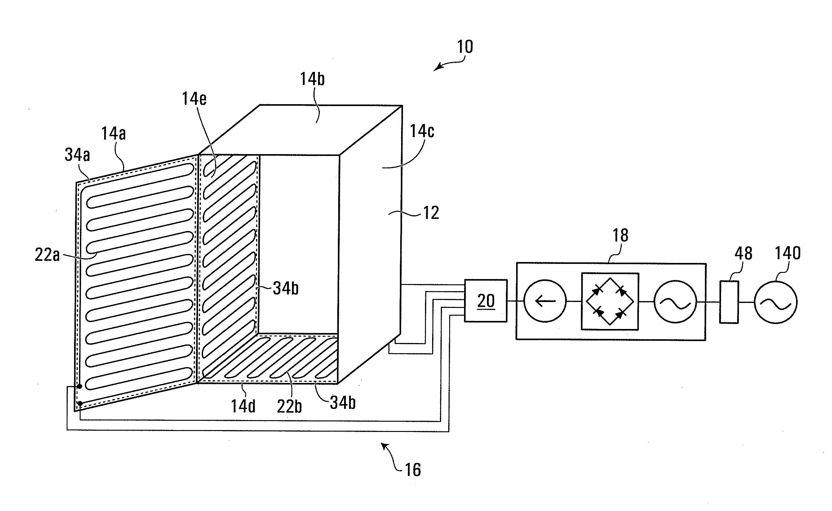
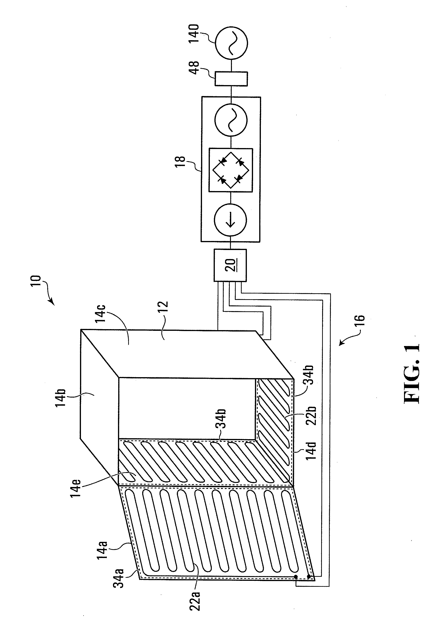
[0024]FIG. 1 depicts a tamper detection system 10, exemplary of an embodiment of the present invention. Tamper detection system 10 is provided to detect tampering with cabinet 12. Cabinet 12 is made up of a plurality of panels 14a, 14b, 14c, 14d and 14e (collectively, panels 14). Panels 14 are usually formed of metal or similar (usually conductive) material, for strength and electrical insulation purposes. Circuit 16 of tamper detection system 10 includes an electrical current source 18, sensor 20, and conductive traces 22a and 22b (collectively, conductive traces 22) on panels 14.

[0025]Conductive traces 22a, 22b span protection regions 34a, 34b respectively (collectively and individually protection region 34). A protection region 34, in this context is the region protected from tampering by system 10. As will be appreciated, the protection region 34 need not be co-extensive with all or any panel 14 of cabinet 12. Instead protection region 34 may simply span a vulnerable region of c...


PUM


Abstract

A cabinet formed of a plurality of panels, includes a tamper detection system that includes an electrical circuit for detecting forming of a hole in a protected region of at least one panels. The electrical circuit includes at least one conductive trace on one of the panels. The conductive trace spans a protected region, wherein the minimum distance from any point in the protected region to the at least one conductive trace does not exceed some defined maximum. An electrical current source provides a current through the conductive trace. A sensor is in electrical communication with the electrical current source to sense a change in current provided to the trace and generate a tamper signal in response thereto.

Description

CROSS-REFERENCE TO RELATED APPLICATIONS[0001]The present application claims priority from U.S. Provisional Patent Application No. 61 / 577,303, filed Dec. 19, 2011 the contents of which are hereby incorporated by reference.FIELD OF THE INVENTION[0002]The present invention relates to tamper detection, and more particularly to cabinets that include tamper sensors and related methods.BACKGROUND OF THE INVENTION[0003]Often cabinets housing electronic equipment or valuables need to be secured against tamper and theft. One way to provide such security is to use an electronic alarm that produces a signal in response to sensed tampering[0004]A common way in which cabinets may be tampered with is by drilling or cutting holes through cabinet panels so that an intruder may gain access to the cabinet interior. Accordingly, existing approaches to detecting cabinet tampering include detection of indicia of drilling.[0005]An approach uses a vibration sensor and possibly a pattern recognition algorit...

Claims


Application Information

Patent Timeline
Patent Type & Authority Applications(United States)
IPC IPC(8): G08B13/00
CPCH02H3/06H02H3/087H02J7/0068G01R23/02G06F17/00G01R19/00G01R19/003G01R19/02G01R19/04G01R19/16528G01R19/16576F16H59/105G01D5/2457G01B7/003G01B7/14
Inventor BUCSA, ANDREIFOSTY, STEPHEN D.W.
Owner TYCO SAFETY PRODS CANADA
Why Eureka
Try Eureka