
Touch pixel structure, touch pixel array substrate and touch display panel

a touch display panel and array substrate technology, applied in the direction of instruments, computing, electric digital data processing, etc., can solve the problems of deteriorating the performance of the electronic apparatus with the optical touch display panel, interference of the signals of the read-out line, etc., and achieve the effect of favorable reliability

Active Publication Date: 2013-06-20
AU OPTRONICS CORP
View PDF4 Cites 17 Cited by
  • Summary
  • Abstract
  • Description
  • Claims
  • Application Information

AI Technical Summary

Benefits of technology

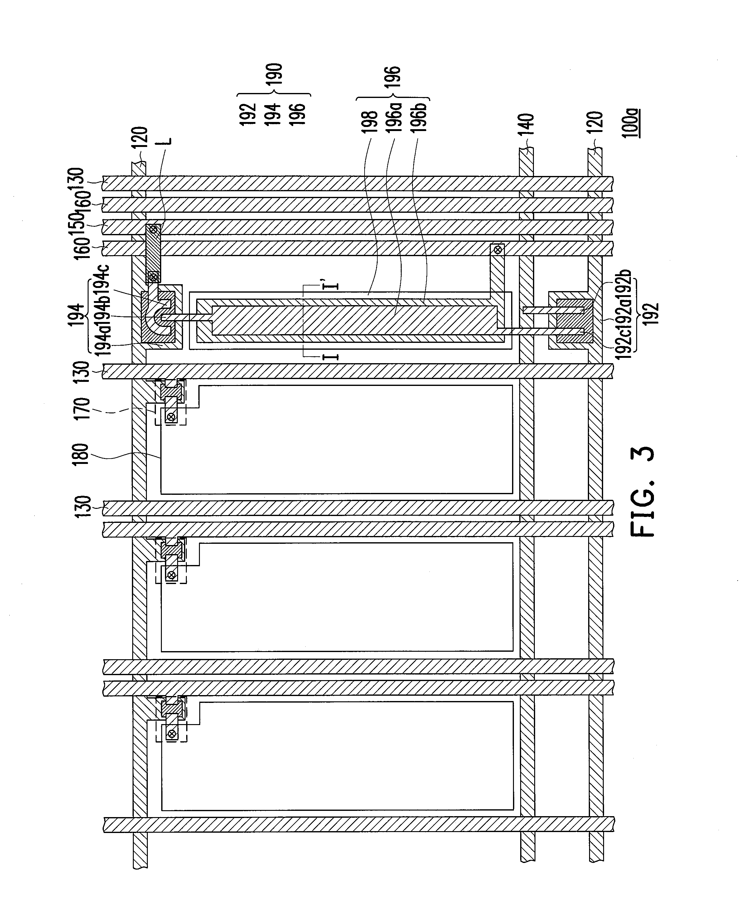
The invention provides a touch pixel array substrate, touch display panel, and touch pixel structure with reliable performance. The substrate has a unique layout where each read-out line is set between two data lines, and two voltage-shielding lines are placed between the read-out line and two data lines. This results in effective shielding between the read-out line and data lines, preventing interference and ensuring good signal transmission. Overall, this technology ensures the best performance of touch display panels.

Problems solved by technology

However, when the read-out lines are configured onto the pixel array substrate, signals of the read-out lines are interfered due to electrical coupling phenomenon between the read-out lines and other circuits.
As such, the touch event cannot be accurately judged, which deteriorates the performance of the electronic apparatus with the optical touch display panel.

Method used


Image

  • Touch pixel structure, touch pixel array substrate and touch display panel
  • Touch pixel structure, touch pixel array substrate and touch display panel
  • Touch pixel structure, touch pixel array substrate and touch display panel

Examples


Embodiment Construction

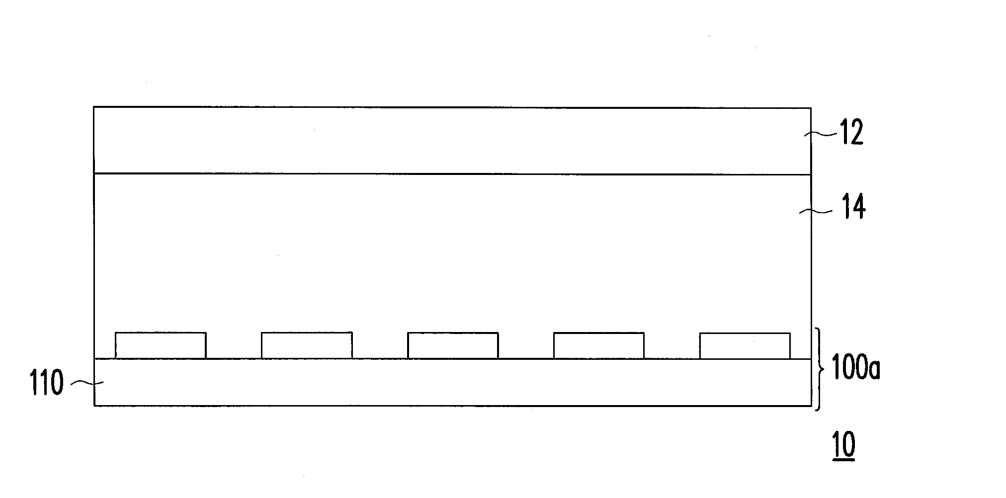
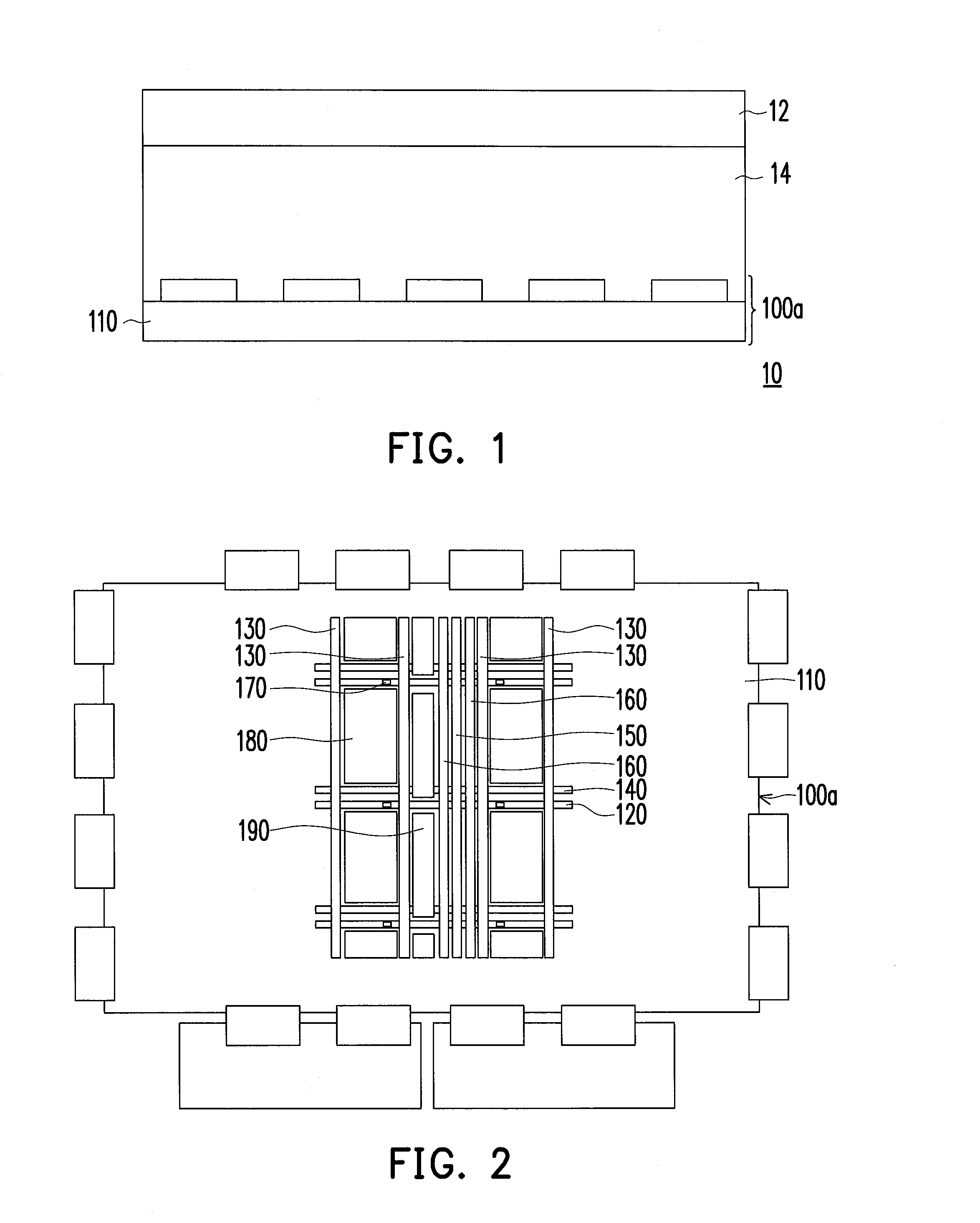
[0022]FIG. 1 is a schematic cross-sectional view illustrating a touch display panel according to an embodiment of the invention. With reference to FIG. 1, the touch display panel 10 described in the present embodiment includes a touch pixel array substrate 100, a second substrate 12, and a display medium 14. The first substrate 110 and the second substrate 12 are glass substrates, reinforced glass substrates, plastic substrates, flexible substrates, or composite substrates containing the above-mentioned substrates, for instance. The touch display panel 10 further includes an opposite electrode (not shown) disposed on the second substrate 12. The display medium 14 may include a non-self-illuminating material (e.g., a liquid crystal layer), an organic self-illuminating material (e.g., an organic electroluminescent layer), an inorganic self-illuminating material, or a combination thereof. Specifically, the display medium 14 may include a liquid crystal material, an electrophoretic disp...


PUM


Abstract

A touch pixel array substrate suitable for a touch display panel includes a first substrate, scan lines, data lines, signal-control lines, read-out lines, voltage-shielding lines, active devices, pixel electrodes, and photo-sensing units. The scan lines, the data lines, the signal-control lines, the read-out lines, and the voltage-shielding lines are located on the first substrate. Each of the read-out lines is located between two adjacent data lines. Each of the voltage-shielding lines is located between one of the read-out lines and one of the data lines. Both sides of each of the read-out lines are adjacent to two voltage-shielding lines. The photo-sensing units are located on the first substrate and electrically connected to the scan lines, the signal-control lines, and the read-out lines correspondingly. A touch display panel and a touch pixel structure are also provided.

Description

CROSS-REFERENCE TO RELATED APPLICATION[0001]This application claims the priority benefit of Taiwan application serial no. 100146920, filed Dec. 16, 2011. The entirety of the above-mentioned patent application is hereby incorporated by reference herein and made a part of this specification.BACKGROUND OF THE INVENTION[0002]1. Field of the Invention[0003]The invention relates to a touch pixel structure, a touch pixel array substrate, and a touch display panel. More particularly, the invention relates to an optical touch pixel structure, an optical touch pixel array substrate, and an optical touch display panel.[0004]2. Description of the Related Art[0005]A man-machine interface (MMI) is a communication medium between human beings and machine. Generally, an electronic apparatus on the market is designed with an MMI for a user to execute various functions of the electronic apparatus conveniently. Since information technologies, wireless mobile communications, and information home applian...

Claims


Application Information

Patent Timeline
IPC IPC(8): G06F3/042
CPCG06F3/0412G06F2203/04107G06F3/0421
Inventor CHUNG, YUEH-HUNGHSU, YA-LINGHUANG, HSUEH-YINGCHENG, YI-RU
Owner AU OPTRONICS CORP
Learn More