Voting-Based Pose Estimation for 3D Sensors

a technology of 3d sensors and data acquisition, applied in image analysis, image enhancement, instruments, etc., can solve the problems of insufficient discrimination and compact surface points of many industrial and real-world objects, and achieve the effect of faster computation and greater accuracy

Active Publication Date: 2013-06-20
MITSUBISHI ELECTRIC RES LAB INC
View PDF9 Cites 59 Cited by
  • Summary
  • Abstract
  • Description
  • Claims
  • Application Information

AI Technical Summary

Benefits of technology

[0010]Carefully selected primitives encode more information compactly and thereby provid

Problems solved by technology

Although oriented surface points (points on the surface of an object with normals) used in the prior art are discriminative for objects with signifi

Method used


Image

  • Voting-Based Pose Estimation for 3D Sensors
  • Voting-Based Pose Estimation for 3D Sensors
  • Voting-Based Pose Estimation for 3D Sensors

Examples


Embodiment Construction

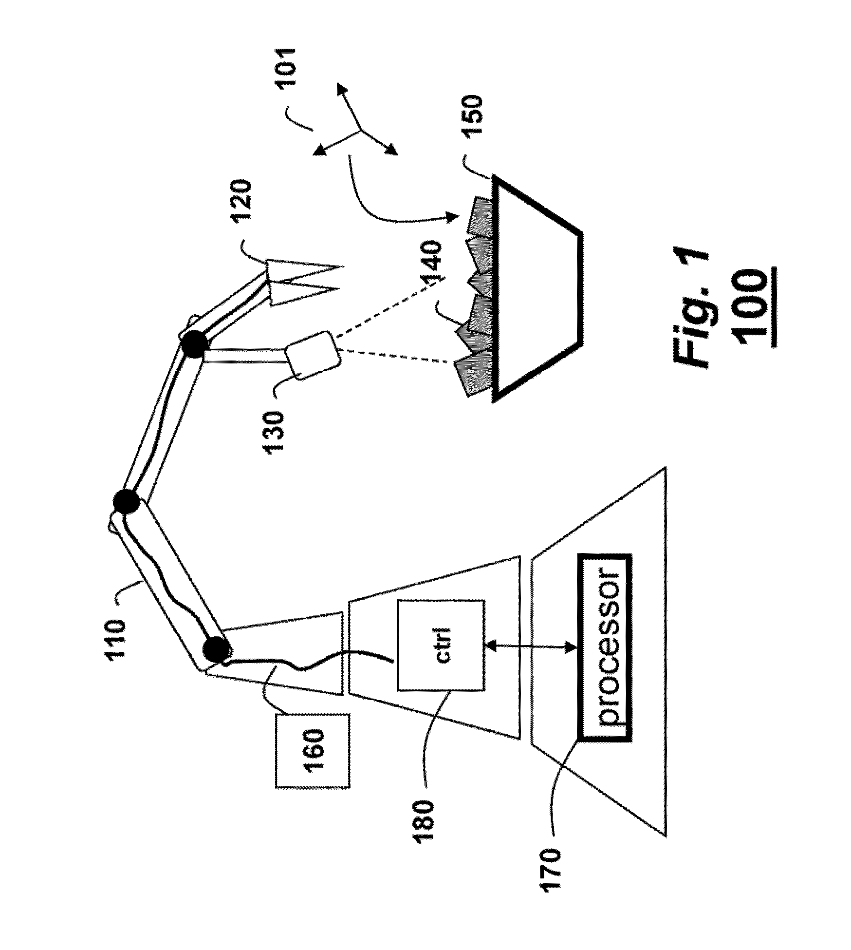
[0016]FIG. 1 shows a system 100 for estimating a pose of an object. The system includes a 6-axis robotic arm 110 with a gripper 120. A 3D sensor 130 is arranged on the arm. The gripper picks objects 140 up from a bin 150 depending on their pose 101. It should be noted that the bin can contain different objects.

[0017]One example 3D sensor uses structured light generated by an infrared laser. Other sensors are also possible. The sensor acquires 3D “point clouds”160 as depth maps of 640×480 pixels. The 3D sensor is calibrated with respect to the robot arm, thereby allowing grasping and picking of an object using the pose.

[0018]The 3D point clouds are processed by a method performed in a processor 170. The processor can include memory and input / output interfaces as known in the art. The method determines the pose, which can be fed back to a controller 180 to direct the arm to pick the object 140.

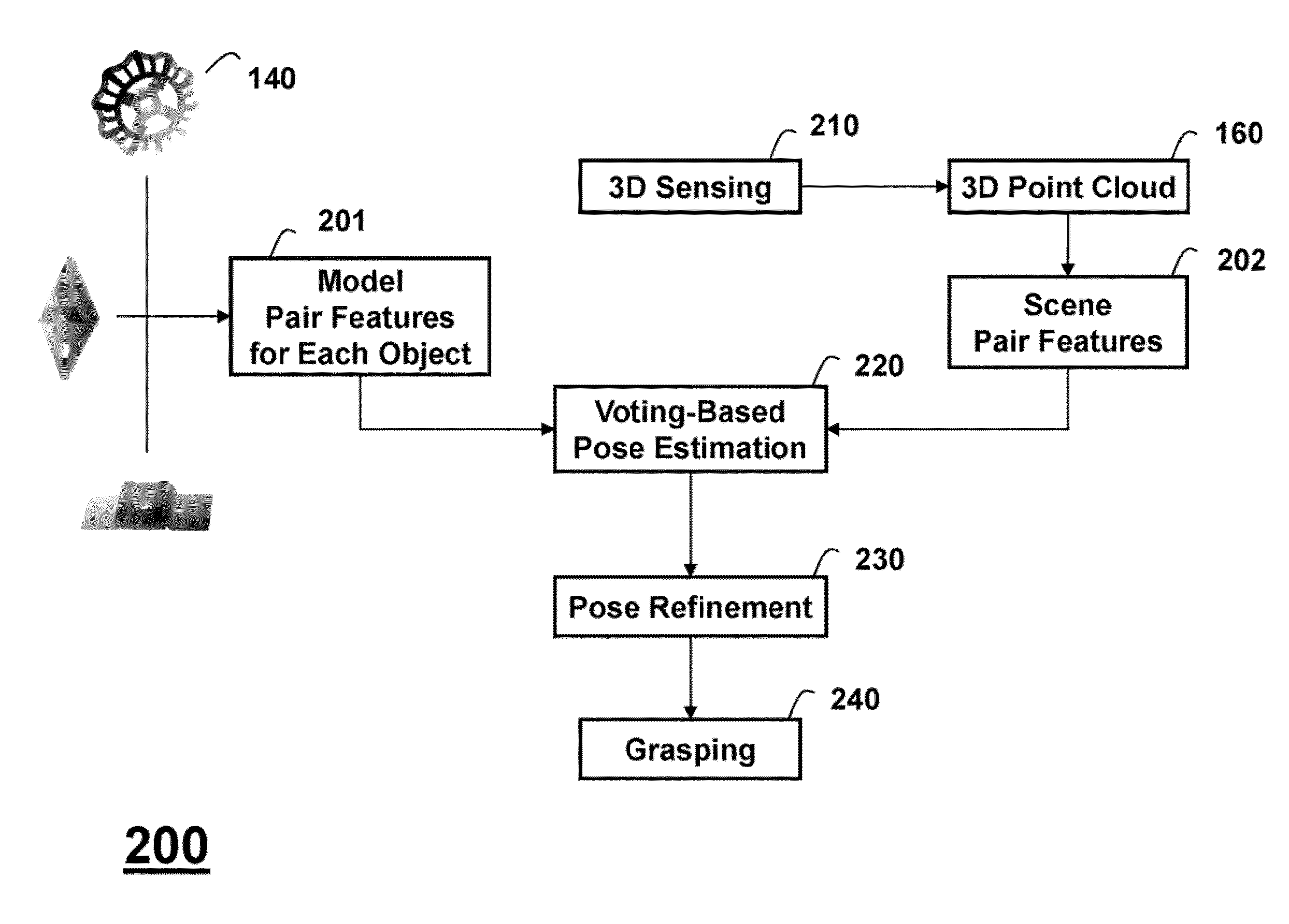
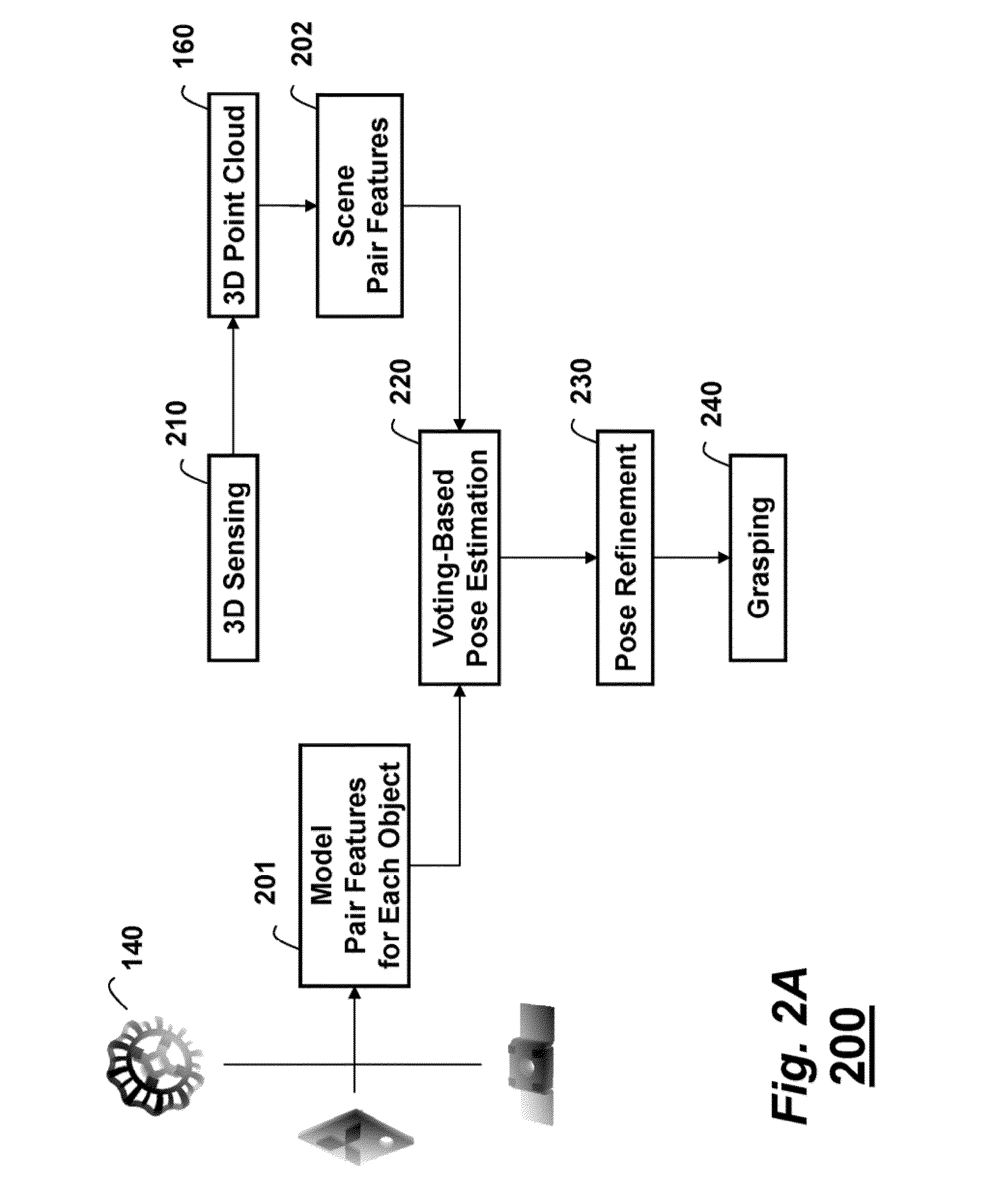
[0019]FIG. 2A shows a block diagram of the method 200, which includes the following steps: 3...


PUM


Abstract

A pose of an object is estimated by first defining a set of pair features as pairs of geometric primitives, wherein the geometric primitives include oriented surface points, oriented boundary points, and boundary line segments. Model pair features are determined based on the set of pair features for a model of the object. Scene pair features are determined based on the set of pair features from data acquired by a 3D sensor, and then the model pair features are matched with the scene pair features to estimate the pose of the object.

Description

FIELD OF THE INVENTION[0001]This invention relates generally to estimating poses of 3D objects, and more particularly to estimating poses from data acquired by 3D sensors.BACKGROUND OF THE INVENTION[0002]The pose of an object has 6-degree-of-freedom (6-DoF), i.e., 3D translation and 3D rotation. The problem of pose estimation refers to finding the pose of an object with respect to a reference coordinate system, usually the coordinate system of a sensor. The pose can be acquired using measurements from sensors, e.g., 2D images, 3D point clouds, with 3D models. Pose estimation plays a major role in many robotics applications such as bin picking, grasping, localization, autonomous navigation, and 3D reconstruction.[0003]Until recently, pose estimation was primarily done using 2D images because cameras are cost effective and allow fast image acquisition. The main problem with 2D images is to match the 2D features with their corresponding 3D features in the model. This becomes challengin...

Claims


Application Information

Patent Timeline
IPC IPC(8): G06K9/00
CPCG06T7/0046G06T2207/30164G06T2207/30108G06T7/0057G06T7/75G06T7/521
Inventor TAGUCHI, YUICHITUZEL, ONCELRAMALINGAM, SRIKUMARCHOI, CHANGHYUNLIU, MING-YU
Owner MITSUBISHI ELECTRIC RES LAB INC
Why Eureka
Try Eureka