
Composite Columnar Structure Having Co-Bonded Reinforcement and Fabrication Method

a columnar structure and co-bonded technology, applied in the direction of pipes, preformed elements, packaging, etc., can solve the problems of adding cost and/or undesired weight to the vehicle or other structure to which the strut is attached, and achieve the effect of improving the ability to resist axial compression loads, improving compression load capability, and little or no weight to the structur

Active Publication Date: 2013-06-20
THE BOEING CO
View PDF7 Cites 19 Cited by
  • Summary
  • Abstract
  • Description
  • Claims
  • Application Information

AI Technical Summary

Benefits of technology

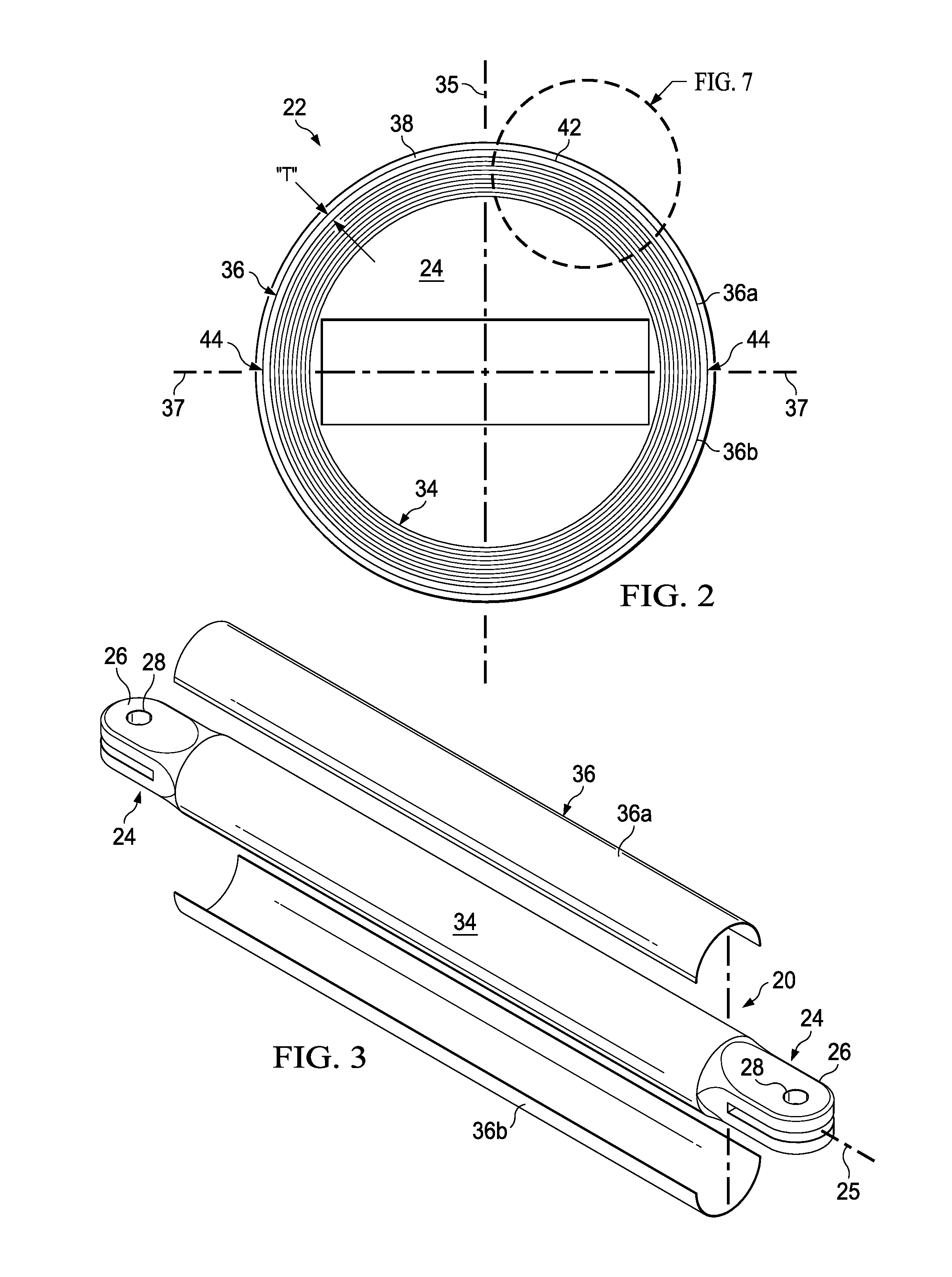
The disclosed embodiments provide a way to make a strong and lightweight columnar structure, like a tubular strut, that can resist axial compression loads. This is done by adding a reinforcement around a laminated plies core, which allows the strut to be designed to carry both compression and tension loads while minimizing the weight. The reinforcement may include corrugations that control wrinkling of the plies during curing. The method includes fabricating the composite laminate core, adding the sleeve-like reinforcement, and then fabricating the outer skin. The result is a strong and lightweight columnar structure that can withstand higher levels of load carrying.

Problems solved by technology

Over-sizing the strut, however, may add cost and / or undesired weight to a vehicle or other structure to which the strut is attached.

Method used


Image

  • Composite Columnar Structure Having Co-Bonded Reinforcement and Fabrication Method
  • Composite Columnar Structure Having Co-Bonded Reinforcement and Fabrication Method
  • Composite Columnar Structure Having Co-Bonded Reinforcement and Fabrication Method

Examples


Embodiment Construction

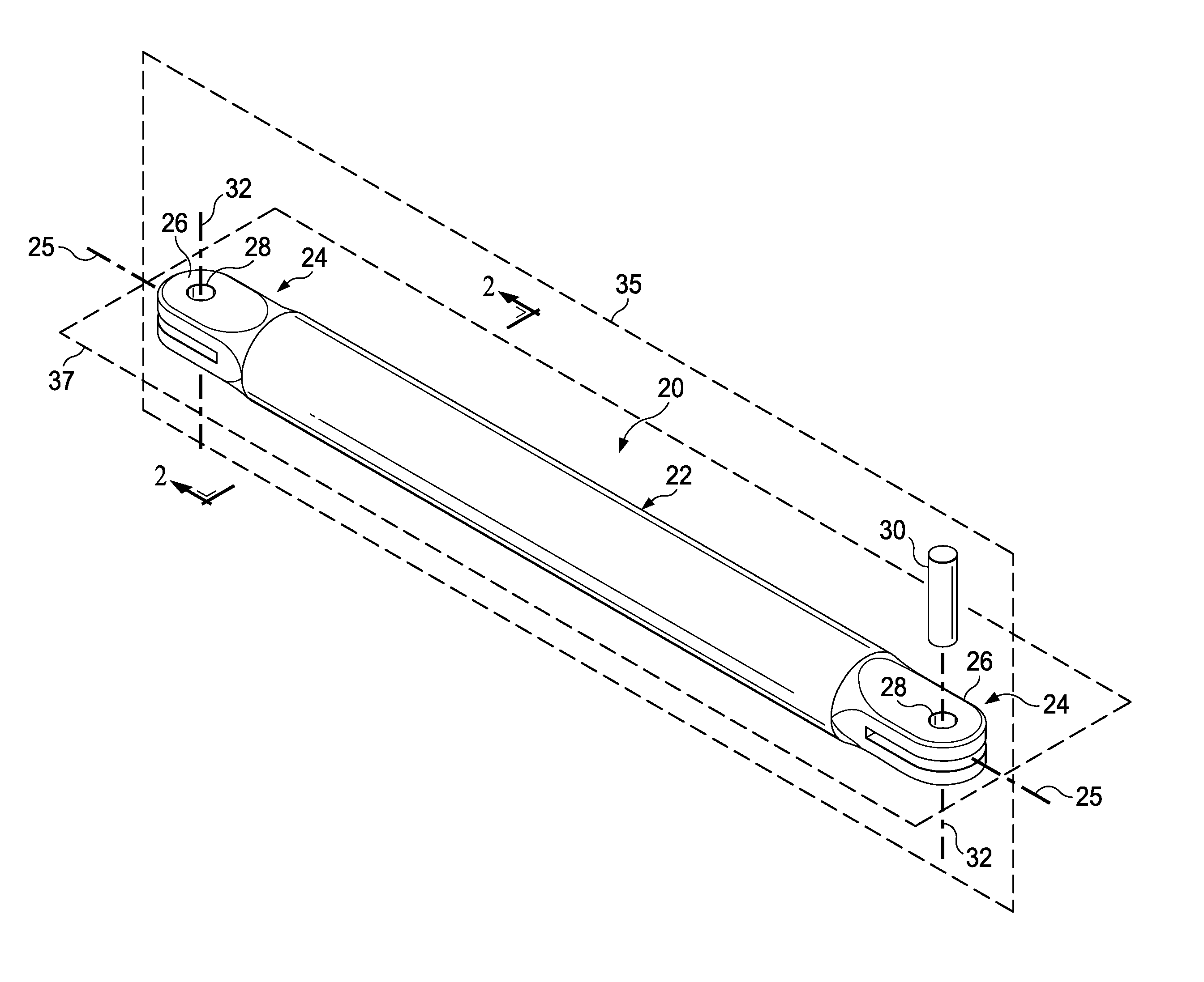
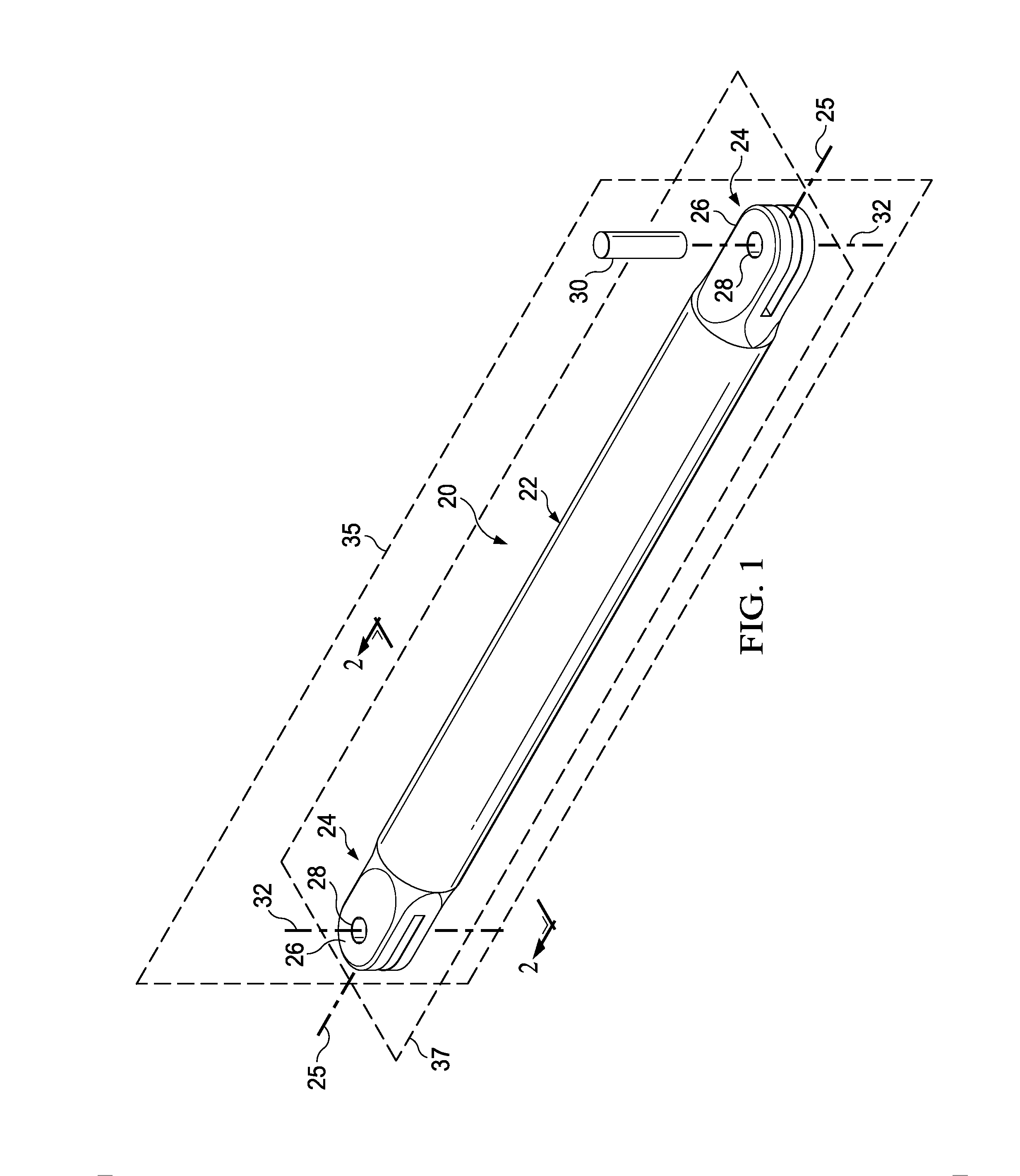
[0025]Referring first to FIG. 1, a composite columnar structure illustrated as an elongate strut 20 includes a generally cylindrical, tubular body 22 and a pair of end fittings 24 for attaching the strut 20 to a structure (not shown). The strut 20 may function to transfer compression loads along the longitudinal axis 25 of the tubular body 22, and may also transfer loads that place the tubular body 22 in tension. Each of the end fittings 24 may be made of a metal such as aluminum or titanium, or a composite or other suitable materials. The end fittings 24 may be fabricated by casting, machining, or other common manufacturing techniques. In applications where the end fittings 24 are formed of composite materials, they may include metallic inserts and / or metallic bushings (not shown).

[0026]Each of the end fittings 24 may include a clevis 26 having a central opening 28 aligned along an axis 32 for receiving a clevis pin 30 that attaches the strut 20 to the structure. The axes 32 of the...


PUM

PropertyMeasurementUnit
columnar structureaaaaaaaaaa
compressiveaaaaaaaaaa
compressive strengthaaaaaaaaaa

Abstract

A columnar structure comprises a generally hollow laminate core, an outer composite skin, and a sleeve-like reinforcement. The sleeve-like reinforcement surrounds the laminate core and is sandwiched between the laminate core and the outer composite skin for reacting compressive loads imposed on the columnar structure.

Description

CROSS REFERENCE TO RELATED APPLICATION[0001]This application is related to co-pending U.S. patent application Ser. No. 13 / 288,491 filed Nov. 3, 2011, which is incorporated by reference herein in its entirety.BACKGROUND INFORMATION[0002]1. Field[0003]The present disclosure generally relates to composite columnar structures, and deals more particularly with a hybrid composite tubular strut internally reinforced to better resist axial compression loads.[0004]2. Background[0005]Columnar structures formed of composites are used in a variety of applications because of their favorable strength-to-weight ratio. For example, composite tubular struts may be used in the aerospace industry as a support or brace for transferring loads in either direction along the longitudinal axis of the strut, thus placing the strut in either compression or tension. Fittings on the ends of the strut provide additional strength at the points of attachment of the strut to a structure.[0006]The tubular struts men...

Claims


Application Information

Patent Timeline
Patent Type & Authority Applications(United States)
IPC IPC(8): B32B1/08B23P17/00B64D27/40
CPCB29L2031/06Y10T428/1355B29C70/543B29C70/088B32B1/08B32B9/005B32B9/047B32B15/14B32B2597/00B29L2031/3076B29K2709/02B29L2031/748B29C70/86B29C70/865B29K2705/00F16C7/026Y10T428/13Y10T29/4998Y10T428/1321B29C70/542Y02T50/40B29C70/08B29C70/38B32B15/08
Inventor STEWART, SAMUEL RAY
Owner THE BOEING CO
Learn More