Ultrasonic diagnostic apparatus and method of displaying ultrasonic image

a diagnostic apparatus and ultrasonic technology, applied in the field of ultrasonic diagnostic equipment, to achieve the effect of easy recognition of the area

Active Publication Date: 2013-06-20
FUJIFILM HEALTHCARE CORP
View PDF9 Cites 5 Cited by
  • Summary
  • Abstract
  • Description
  • Claims
  • Application Information

AI Technical Summary

Benefits of technology

[0021]According to the present invention, since the area of the object organ corresponding to the elasticity value range displayed as the three-dimensional elasticity image can be visually shown on at least one of the section image and the two-dimensional elasticity image, the operator can easily recognize that area. The setting of the elasticity value range can readily provide the three-dimensional elasticity image in the desired area.

Problems solved by technology

In the typical rendering method in which voxel values are simply accumulated, a problem occurs in which the elasticity values are accumulated to provide the three-dimensional elasticity image including distorted elasticity characteristics of a living organ, so that the intensity data of the monochrome section image is used to determine the voxel having the highest contribution on the line of sight, and the elasticity value of that voxel is used as the elasticity value of the two-dimensional projection plane to produce the three-dimensional elasticity image.

Method used


Image

  • Ultrasonic diagnostic apparatus and method of displaying ultrasonic image
  • Ultrasonic diagnostic apparatus and method of displaying ultrasonic image
  • Ultrasonic diagnostic apparatus and method of displaying ultrasonic image

Examples


embodiment 1

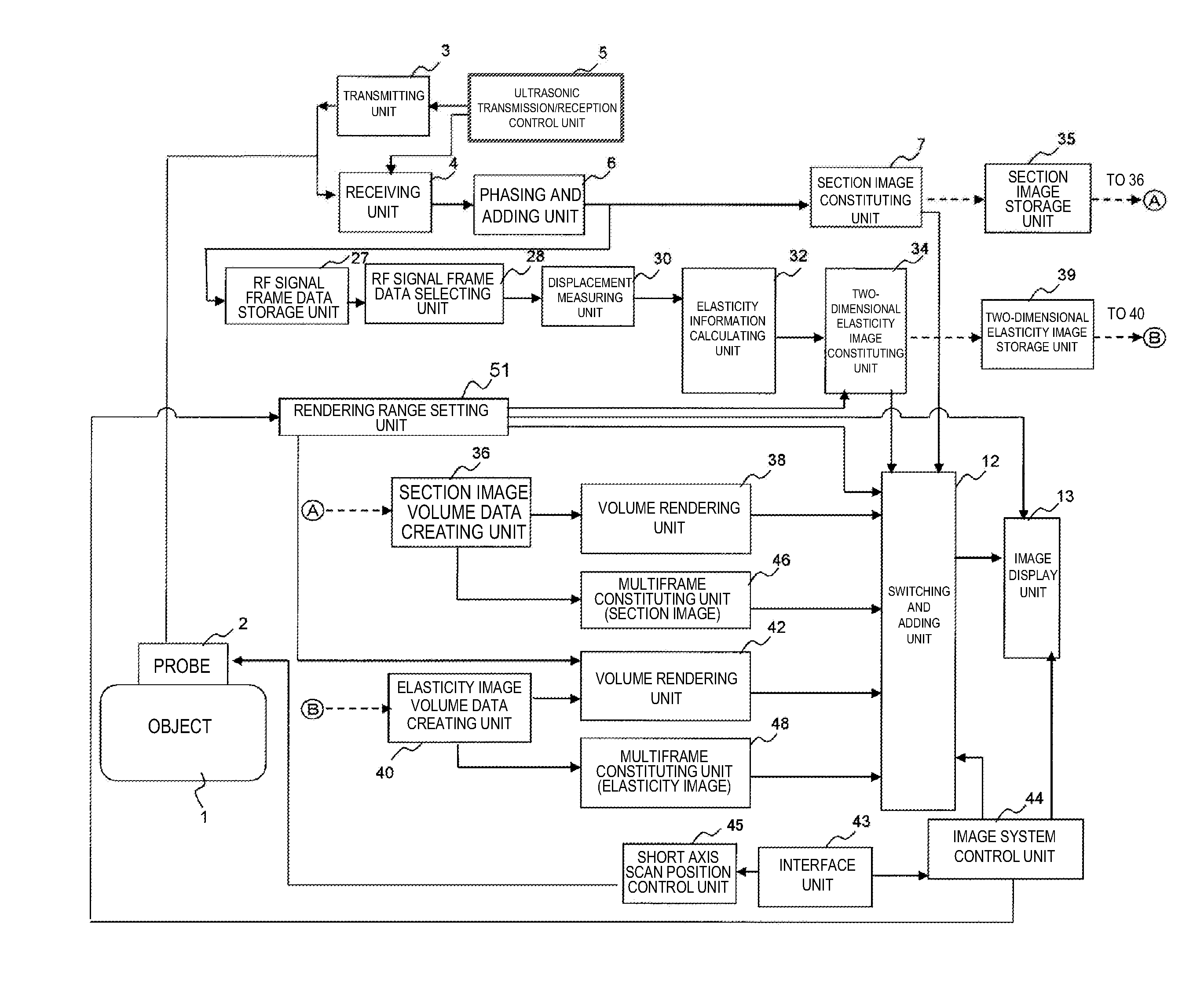
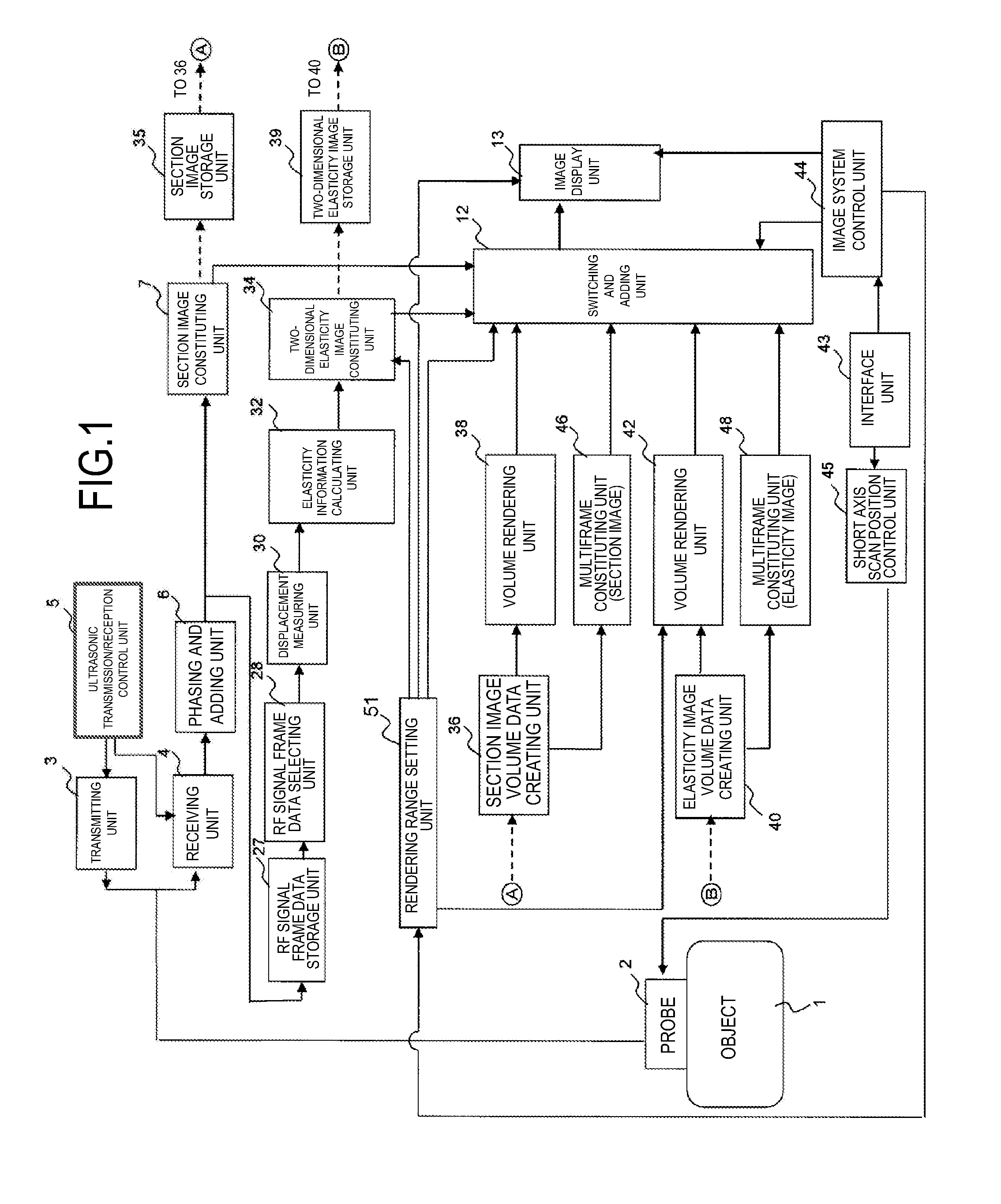
[0078]The ultrasonic diagnostic apparatus of Embodiment 1 includes the section image constituting unit 7 which produces the section image of the object using the received signal as a result of the ultrasonic transmitted into the object, the two-dimensional elasticity image constituting unit 34 which processes the signal to produce the two-dimensional elasticity image for the elasticity value representing the elasticity, the rendering unit 42 which produces the volume data formed of the plurality two-dimensional elasticity images, and selects and renders the elasticity value data of the volume data included in the desired elasticity value range to produce the three-dimensional elasticity image for the elasticity value data within the elasticity value range, and the display unit 13 which displays the three-dimensional elasticity image and at least one of the two-dimensional elasticity image and the section image showing the area associated with the elasticity value range. In the metho...

embodiment 2

[0100]In Embodiment 2, the area outside the elasticity value range set as the rendering range is transparently displayed in the two-dimensional elasticity image of the combined image displayed in the left area on the screen 100 as shown in FIG. 7.

[0101]Specifically, the following expressions (21) to (26) are used in putting the weight on the two-dimensional elasticity image with the mask M1(x,y) at steps 62 and 64 of FIG. 5 in Embodiment 1.

[0102]When M1(x,y)=1, then

D(R)(x,y)=E(R)(x,y)×r+C(R)(x,y)  expression (21)

D(G)(x,y)=E(G)(x,y)×r+C(G)(x,y)  expression (22)

D(B)(x,y)=E(B)(x,y)×r+C(B)(x,y)  expression (23)

[0103]when M1(x,y)=0, then

D(R)(x,y)=C(R)(x,y)  expression (24)

D(G)(x,y)=C(G)(x,y)  expression (25)

D(B)(x,y)=C(B)(x,y)  expression (26)

[0104]As apparent from the expressions (24) to (26), the two-dimensional elasticity image 112 is not combined in the area (the area of M1(x,y)=0) outside the elasticity value range set as the rendering range, so that the two-dimensional elasticity i...

embodiment 3

[0106]In Embodiment 3, at steps 62 and 65 of FIG. 5 in Embodiment 1, the combined image is produced by filling in the area of the elasticity value range set as the rendering range with a predetermined single color corresponding to the elasticity value of that area.

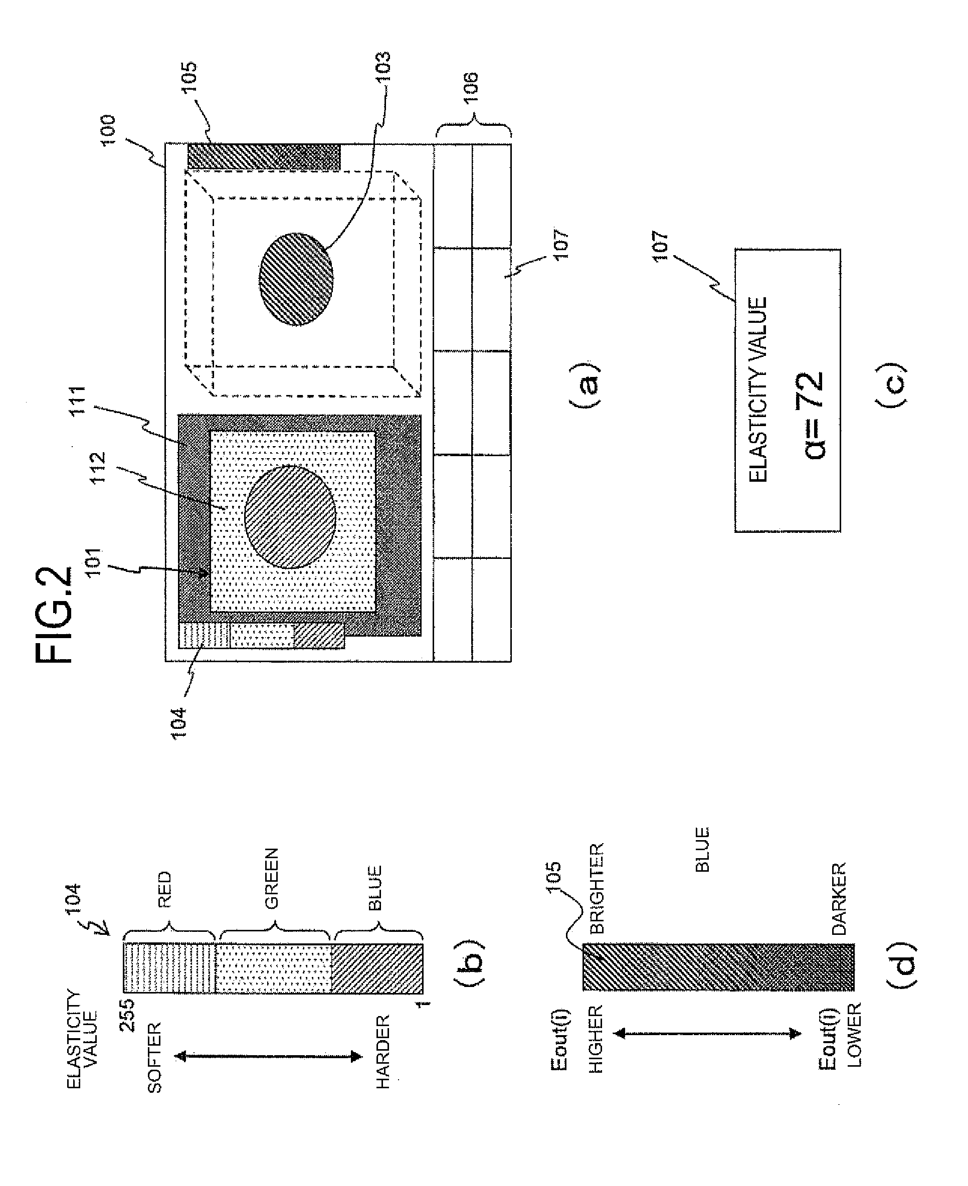
[0107]Specifically, the following expressions (27) to (32) are used in putting the weight on the two-dimensional elasticity image with the mask M1(x,y) 110 as shown in FIG. 8(a) at steps 62 and 64 in Embodiment 1.

[0108]When M1(x,y)=1, then

D(R)(x,y)=K(R)(x,y)  expression (27)

D(G)(x,y)=K(G)(x,y)  expression (28)

D(B)(x,y)=K(B)(x,y)  expression (29)

[0109]When M1(x,y)=0, then

D(R)(x,y)=E(R)(x,y)×r×w+C(R)(x,y)  expression (30)

D(G)(x,y)=E(G)(x,y)×r×w+C(G)(x,y)  expression (31)

D(B)(x,y)=E(B)(x,y)×r×w+C(B)(x,y)  expression (32)

[0110]K(R), K(G), and K(B) represent hues predefined in accordance with the elasticity values of the elasticity value range (M1(x,y)=1) set as the rendering range. For example, when the elasticity value range ...


PUM


Abstract

To provide an ultrasonic diagnostic apparatus capable of producing a three-dimensional image of an object for an organ region within a range of elasticity values desired by an operator and allowing the operator to recognize the region easily, elasticity value data included in a desired elasticity value range among elasticity value data constituting a volume data are selected and rendered. Whereby, a three-dimensional elasticity image in the set elasticity value range is produced. An area corresponding to the elasticity value range is displayed on at least one of a two-dimensional elasticity image and a section image.

Description

TECHNICAL FIELD[0001]The present invention relates to an ultrasonic diagnostic apparatus which uses ultrasonic waves to display an ultrasonic image of a diagnostic part within an object, and more particularly, to an ultrasonic diagnostic apparatus capable of displaying an elasticity image representing the hardness of a living organ of the object as a three-dimensional image.BACKGROUND ART[0002]As described in Patent Literatures 1 and 2, a conventional ultrasonic diagnostic apparatus transmits ultrasonic into an object, receives the ultrasonic reflection echo signal of a living organ from the reflected wave, performs signal processing on the signal to produce and display a monochrome section image (B mode image) of a diagnostic part having intensities as the ultrasonic reflectivities.[0003]Patent Literature 2 has disclosed a technique involving performing three-dimension coordinate conversion from the monochrome section image and its taking position to obtain three-dimensional volume...

Claims


Application Information

Patent Timeline
Patent Type & Authority Applications(United States)
IPC IPC(8): A61B8/00A61B8/14A61B8/08
CPCA61B8/463A61B8/466A61B8/485A61B8/5223A61B8/483A61B8/4461A61B8/467A61B8/5207A61B8/54A61B8/14A61B8/469G16H50/30
Inventor INOUE, SHINSUKE
Owner FUJIFILM HEALTHCARE CORP
Why Eureka
Try Eureka