Valve for shock absorbers

a valve and shock absorber technology, applied in the direction of shock absorbers, vibration dampers, springs/dampers, etc., can solve the problems of loss of pedaling efficiency, limited sensitivity of the damper valve, and limited potential of the flow-sensitive damper to distinguish between bumps and movements of the vehicle chassis, so as to improve the suspension performance

Active Publication Date: 2013-06-27
EKO SPORT INC
View PDF7 Cites 34 Cited by
  • Summary
  • Abstract
  • Description
  • Claims
  • Application Information

AI Technical Summary

Benefits of technology

[0017]The ability of a suspension damper to control unwanted chassis movements and yet compliantly absorb bumps is enhanced by the present invention insofar as damper valve closure in the invention is maintained by a force that moderates as the valve opens. The higher the force holding the valve in the closed position, the less unwanted chassis movement will occur. However, the lower the force urging closure of the valve once the valve opens, the longer the period of hydraulic fluid flow during the traversal of a bump and the less jounce will be transmitted to the vehicle (i.e., the better the vehicle will absorb the shock). A retrogressive component of biasing force on the valve also enhances suspension performance during rebound. Valves requiring a lower force to remain in the open position relative to the biasing force acting upon them in the closed position approach the performance ideal of rapid recovery from deep compression followed by smooth deceleration as extension is reached.
[0018]A preferred embodiment of the present invention is a damper with a compression and / or rebound valve biased toward the closed position either partly or entirely by continuous magnetic force. The magnetically sprung valve may be combined with an external mechanical adjustment means. The adjustment means permits the magnetic force to be varied, or permits a non-magnetic biasing force acting in combination with magnetism to be altered so as to change the relative amount of overall valve closing force due to magnetism. Since the maximum rate of fluid flow through the compression or rebound circuit of the damper determines the peak pressure that can be exerted on the magnetically sprung valve, auxiliary valves that vary maximum rate of flow can also dynamically interact with the magnetically sprung valve to give the damper its performance features.
[0020]In an alternative embodiment of the invention, a mechanical spring can be used to close the valve with a magnetic spring that urges the valve to the open position once pressure due to compression has opened the valve. A coil spring biases the valve closed, and is combined with a structure in which magnetic attraction tends to keep the valve open once the valve has opened by overcoming the coil spring bias. The attraction between a valve component and an opener becomes substantial once the valve opens, and as the valve component moves farther from the closed position, the magnetic attraction increases. This thereby counteracts the increase in force tending to close the opened valve by increasing the magnetic attraction that tends to open the valve as the compression of the coil spring increases.
[0029]In another embodiment, a shock absorber may include a housing having a cylindrical sidewall, a first chamber containing fluid, and a second chamber containing fluid. A valve may be in a fluid communication path between the first chamber and the second chamber. The valve may have an orifice component and an orifice blocker component. The orifice component and the orifice blocker component may be configured to move relative to one another between at least an open valve position in which the orifice blocker component is spaced from the orifice component and a closed valve position in which the orifice blocker component is adjacent, and substantially obstructs fluid from flowing through, the orifice. A magnetically attractive element may be positioned adjacent the orifice blocker component, whereby the orifice blocking component may be urged toward one of the valve positions by a magnetic bias formed by the magnetically attractive element and the orifice blocker component. Upon sufficient inertial effect of force upon at least one of the orifice blocking component and the magnetically attractive element, the magnetic bias between the magnetically attractive element and the orifice blocker component may be exceeded, thereby permitting the orifice blocker component to move from one of the valve positions to the other of the valve positions.

Problems solved by technology

Though superior to simple orifice dampers, dampers with flow-sensitive shims have limited potential for distinguishing between bumps and movements of the vehicle chassis.
Conventional suspension damping allows unwanted “bobbing” of the bicycle and loss of pedaling efficiency when the rider's weight shifts in this way.
Although a preloaded, sprung damper valve may open along a gently sloping load vs. deflection plot once its force threshold is reached, its sensitivity nevertheless is limited by the continued upward direction of the gradient.
But this acceleration, with its attendant peak pressure, fades long before the wheel finishes surmounting the bump, thereby allowing the valve to close prematurely under the countervailing force of the spring.
As this transmission of bump force increases, the ride becomes harsher and the vehicle's traction over irregular surfaces becomes poorer.
Similarly, in the case of rapid extension of a shock in which the rebound damping circuit is governed by a preloaded, sprung valve, the spring that urges the valve to close may overcome the force exerted by oil flow through the rebound circuit before the shock absorber fully extends, thereby reducing the available stroke of the suspension and adversely affecting ride quality.
Valves biased toward the closed position by mechanical springs necessarily limit the extent to which dampers can achieve this objective, because the spring force applied increases as the valve is opened further, thereby requiring an increasing force to maintain the valve in an open position at a time when the valve-opening force inherently decreases.
Inertia valves are subject to an analogous problem due to the progressively increasing resistance of a coil or leaf spring as it deflects.
The result, again, is transmission of bump force to the chassis.
The inertia imparted by the spring to the blocker element may vary undesirably the response of the valve to accelerations of the vehicle wheel as it traverses bumps of different sizes at different frequencies.

Method used


Image

  • Valve for shock absorbers
  • Valve for shock absorbers
  • Valve for shock absorbers

Examples


Embodiment Construction

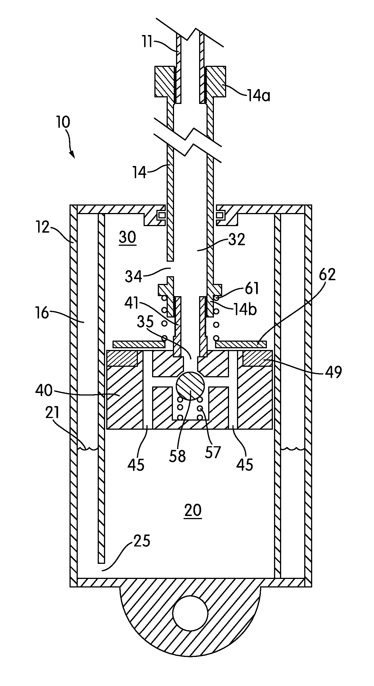
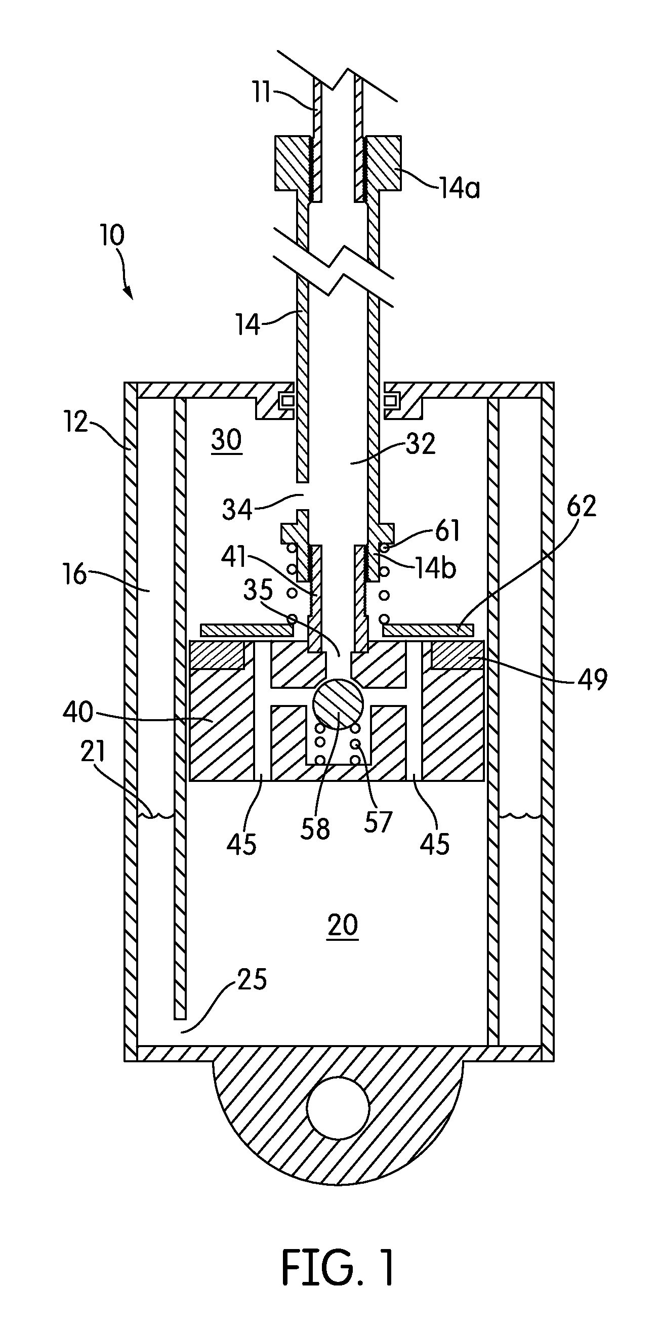
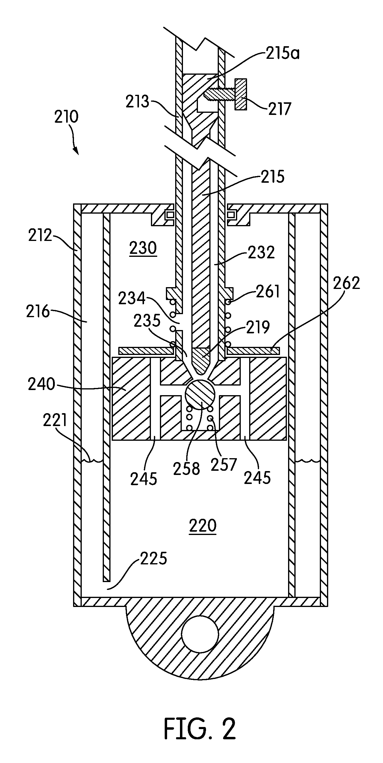
[0063]In the present disclosure, a plurality of valves are disclosed and described as being used in connection with one or more shock absorbers. Each of these valves is shown as being positioned between two fluid-filled chambers and functions generally to control the flow of fluid between the two chambers. In many embodiments, the disclosed valves control the flow from a first one of the chambers to a second one of the chambers in one manner and control the flow from the second one of the chambers back to the first one of the chambers in a different manner. The flow of fluid from the first to the second chamber may accompany a compression stroke of the shock absorber. The flow of fluid from the second to the first chamber may accompany a rebound stroke of the shock absorber. The combination of the compression stroke and the rebound stroke of the shock absorber may be considered a stroke of the shock absorber.

[0064]Although each valve is shown as being positioned directly between two...


PUM


Abstract

A shock absorber having a valve controlling the flow rate of fluid between a compression chamber and a rebound chamber in a housing and separated by a piston. The valve has an orifice component and a blocker component, one of which has a permanent magnet, and the other of which has a magnetically permeable material. Upon the application of sufficient fluid pressure, the blocker component is forced away from the orifice component, despite the magnetic bias that tends to attract the two structures. Because the magnetic force decreases as the two components are spaced farther apart, the shock absorber has excellent performance characteristics. Alternatively, a mechanical spring urges the blocker closed, and magnetic attraction between the blocker and a spaced opener mitigates the increased force of the compressed spring tending to close the valve.

Description

CROSS-REFERENCES TO RELATED APPLICATIONS[0001]This is a continuation-in-part of U.S. application Ser. No. 13 / 345,197, filed Jan. 6, 2012, which is a divisional application of U.S. application Ser. No. 11 / 501,996 filed Aug. 10, 2006, now U.S. Pat. No. 8,104,591, issued Jan. 31, 2012, which claimed the benefit of U.S. Provisional Application No. 60 / 707,385 filed Aug. 11, 2005. All these applications are incorporated herein by reference.STATEMENT REGARDING FEDERALLY-SPONSORED RESEARCH AND DEVELOPMENT[0002](Not Applicable)REFERENCE TO AN APPENDIX[0003](Not Applicable)BACKGROUND OF THE INVENTION[0004]1. Field of the Invention[0005]The invention relates generally to suspension components on vehicles, and more particularly to a shock absorber with a damper valve that incorporates magnetic bias to improve valve performance. Such a device may be referred to as a threshold valve.[0006]2. Description of the Related Art[0007]Conventional shock absorbers employ a piston in a cylinder containing ...

Claims


Application Information

Patent Timeline
Patent Type & Authority Applications(United States)
IPC IPC(8): F16F9/34F16F9/516
CPCF16F9/34F16F2222/06F16F9/461F16F9/516
Inventor BAREFOOT, DAREK C.
Owner EKO SPORT INC
Why Eureka
Try Eureka