Electron beam sterilizer for cap

Active Publication Date: 2013-06-27
SHIBUYA IND CO LTD
View PDF0 Cites 6 Cited by
  • Summary
  • Abstract
  • Description
  • Claims
  • Application Information

AI Technical Summary

Benefits of technology

[0008]Therefore, an object of the present invention is to provide an electron beam cap-sterilizer in which the radiation distance is shortened in comparison with a c

Problems solved by technology

Therefore, the caps rotate very little because of the friction, and thus,

Method used


Image

  • Electron beam sterilizer for cap
  • Electron beam sterilizer for cap
  • Electron beam sterilizer for cap

Examples


Embodiment Construction

[0014]An embodiment of the present invention will be described below with reference to the drawings.

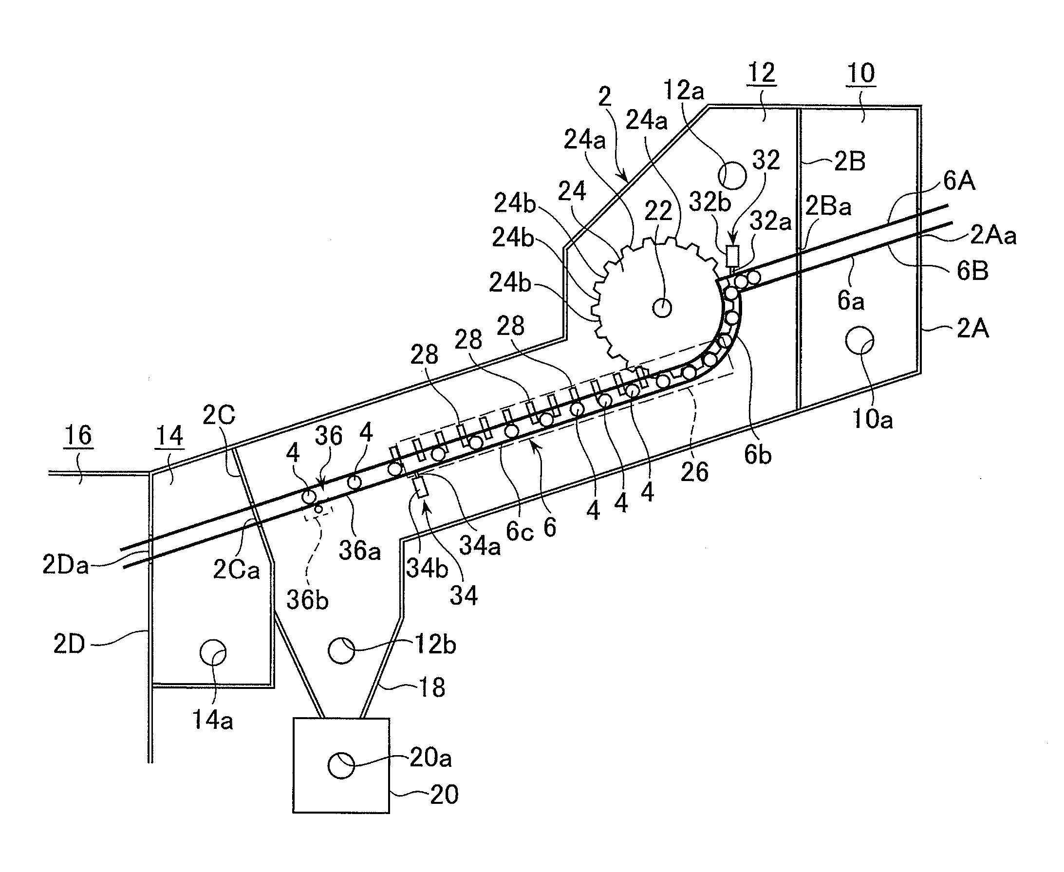
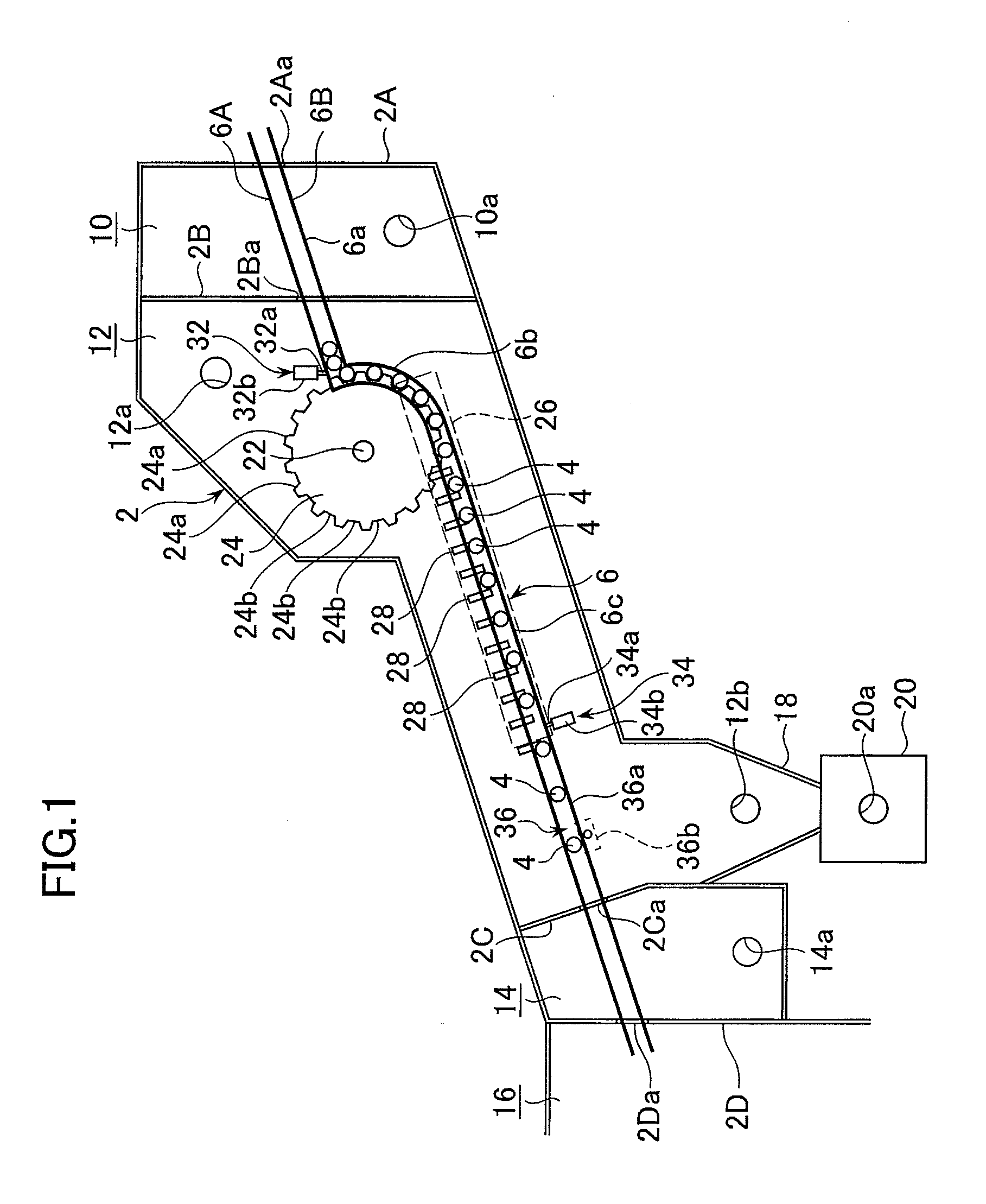
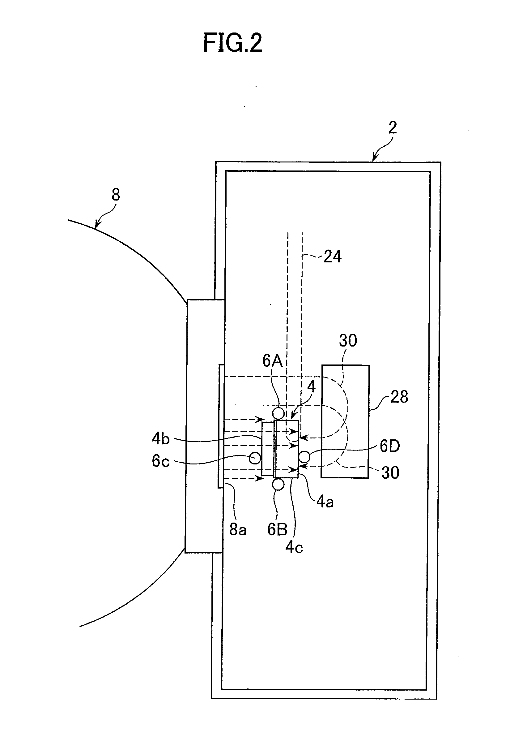
[0015]An electron beam cap-sterilizer has an aseptic chamber 2, divided into a plurality of chambers, in which a conveying passage 6 is provided through which caps 4 are conveyed. The caps 4 conveyed through the conveying passage 6 are sterilized by electron beams emitted by an electron beam radiating device 8 (see FIG. 2), and then transferred to a capping apparatus (not shown).

[0016]The aseptic chamber 2 is divided into a front chamber 10, which is located in the furthest upstream section of the aseptic chamber 2 where caps 4 are supplied from the outside, a sterilizing chamber 12 in which a rotational conveying device and an electron beam radiating device 8 are disposed, and a rear chamber 14 provided immediately downstream of the sterilizing chamber 12. A capping chamber 16, in which a capping apparatus (not shown) is mounted, is connected to the downstream side of the rear chambe...


PUM


Abstract

An electron beam cap-sterilizer radiates an electron beam onto caps while the caps are continuously conveyed. The caps are conveyed in the restricting conveying section while the movements of the caps are restricted, so that the caps roll down freely and separately from each other in the free conveying section. The electron beam radiating device emits electron beams onto the inside of the caps in the lateral direction while the caps are conveyed in the free conveying section. A deflecting device is provided in the free conveying section. The deflecting device is located at the opposite side of the electron beam radiating device to deflect the electron beams emitted by the electron beam radiating device onto the outside of the caps.

Description

BACKGROUND OF THE INVENTION[0001]1. Field of the Invention[0002]The present invention relates to an electron beam sterilizer for caps, in which caps are irradiated by an electron beam and sterilized while they are conveyed.[0003]2. Description of the Related Art[0004]Conventionally, there is known an electron beam cap-sterilizer in which caps are irradiated by an electron beam and sterilized while the caps are continuously conveyed. In such an electron beam cap-sterilizer utilizing an electron beam, a cap chute, which is disposed inclined in a downward direction, is usually used as a conveying device for supplying the caps to an electron beam radiating device, as disclosed in Japanese Unexamined Patent Publication (Translation of PCT Application) No. 2011-520713. In the electron beam cap-sterilizer disclosed in this publication, caps are separated one by one using a star-wheel, and are sent out to the cap chute, in which each of the caps is rolled down and is irradiated by an electr...

Claims


Application Information

Patent Timeline
IPC IPC(8): A61L2/08
CPCA61L2/087G21K5/10B65B55/08B67B3/003
Inventor NAKA, TOSHIAKINISHINO, YUKINOBUNISHI, TOKUOKOUDO, RYOJIMASUMOTO, SATOSHIWATANABE, SOMAHIROSAWA, YUSUKEFUJITA, MITSUHIRO
Owner SHIBUYA IND CO LTD
Why Eureka
Try Eureka