Active suspension system and method

a passive suspension and suspension system technology, applied in the direction of resilient suspensions, springs/dampers, vehicle components, etc., can solve the problems of insufficient or excessive movement of the passenger compartment, the inability of passive suspension systems to rapidly produce active forces, and the undesirable pitch and roll motion of the passenger compartment cannot be properly suppressed, so as to improve the dynamic performance, improve the effect of stability and reliability

Active Publication Date: 2013-06-27
HONG KONG PRODUCTIVITY COUNCIL
View PDF11 Cites 24 Cited by
  • Summary
  • Abstract
  • Description
  • Claims
  • Application Information

AI Technical Summary

Benefits of technology

[0071]Advantageously, the present invention provides improved dynamic performance over passive and hydraulic suspension systems as the controller unit is able to rapidly regulate movement of the linear switched actuator to provide active forces in response to sensed road irregularities which are suitably precise to alleviate pitch and roll motions and to keep the wheels in contact with the ground surface.
[0072]Advantageously, the present invention provides more reliable operation than existing hydraulic-based systems due to the lack of need for oil / air pumps, tanks and other components which are susceptible to leakage problems and require ongoing maintenance. The present invention may also be more reliable than existing electromagnetic suspension systems utilising permanent magnets because the there is no problem with demagnetisation of the permanent magnets which compromises performance. Also, no phased windings are disposed on the translator projections which alleviates weight being unduly placed on the translator and translator shaft in use. Also, the phased windings on the stator projections may be electrically isolated from each other to provide higher fault tolerance.
[0073]Also advantageously, the present invention provides a relatively simpler structure and fewer components compared to hydraulic and permanent-magnet based systems. Accordingly, the present invention may be cheaper to manufacture particularly in mass production. It is also more efficient to produce due to the simplicity of its structure, the relatively few components, and the relatively simple interconnections between the component parts.
[0074]Linear switched reluctance actuators are relatively robust and suitable for use in high temperatures and harsh operating environments so as to provide versatility in application.

Problems solved by technology

Passive suspension systems consisting of mechanical springs and dampers often fail to meet the above objectives due to the tendency of mechanical springs being either too hard or too soft resulting in insufficient or excessive movement of the passenger-carrying compartment respectively in response to road shocks.
Passive suspension systems also cannot produce active forces rapidly to absorb road shocks and therefore undesirable pitch and roll motions of the passenger-carrying compartment cannot be properly suppressed.
Active suspension systems, which typically comprise hydraulic or electromagnetic actuators, provide improved performance over passive suspension systems but still exhibit deficiencies of their own.
Accordingly, the production time and costs are relatively high.
Furthermore, hydraulic systems tend to have low dynamic response and low reliability due to oil / air leakage and other faults which necessitate regular ongoing maintenance.
Electromagnetic active suspension systems based on permanent-magnet actuators suffer from similar problems as those of hydraulic type systems in terms of the complexity of their structures and components which exacerbates production costs.
Additionally, the reliability in performance of existing electromagnetic active suspension systems is adversely affected by the tendency of the permanent magnets to demagnetise over time.
The above-described deficiencies in existing suspension systems compromises passenger ride comfort and safety and there is a perceived need to address such problems.

Method used


Image

  • Active suspension system and method
  • Active suspension system and method
  • Active suspension system and method

Examples


Embodiment Construction

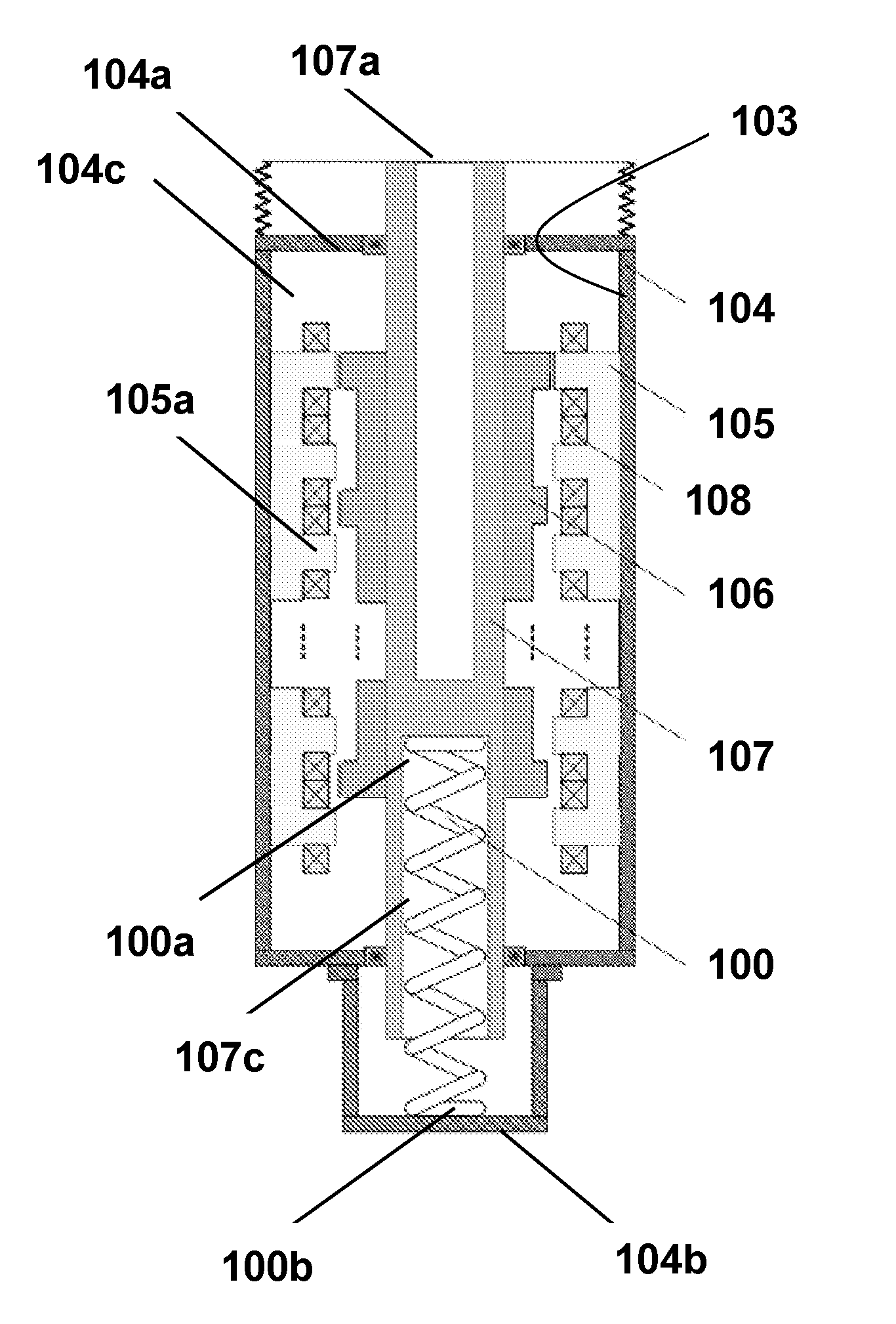
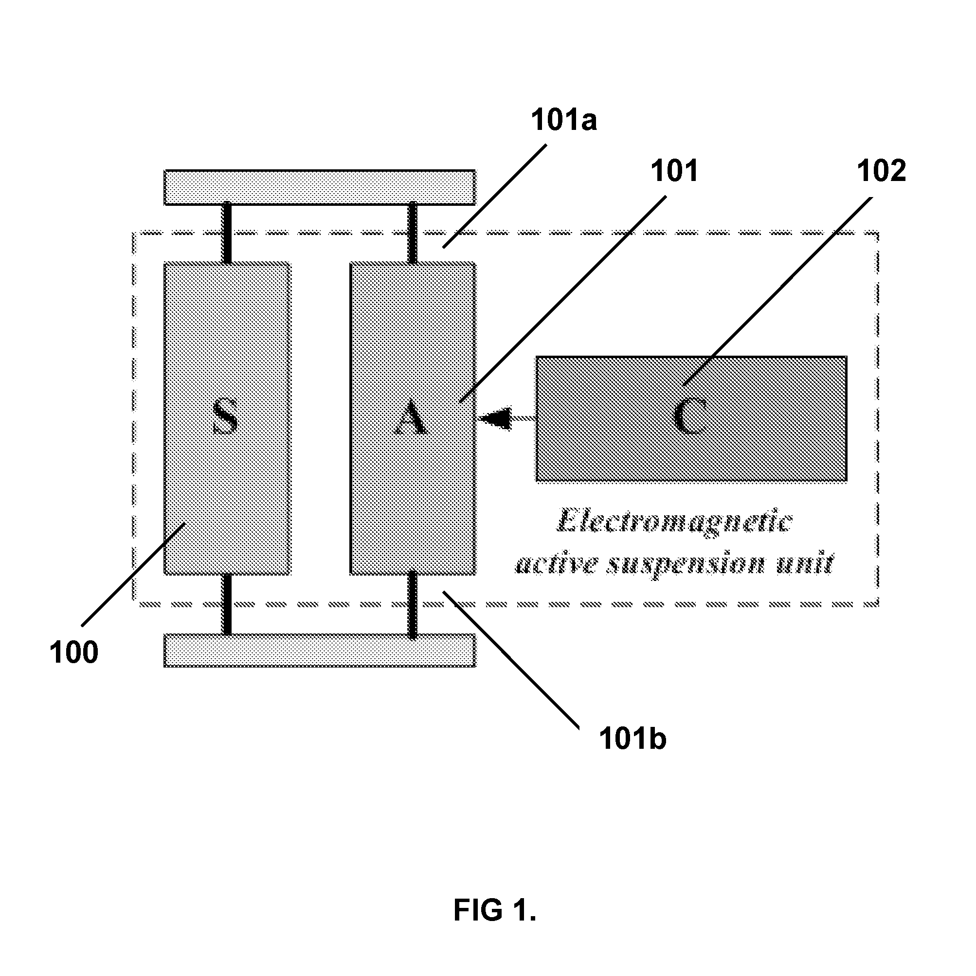
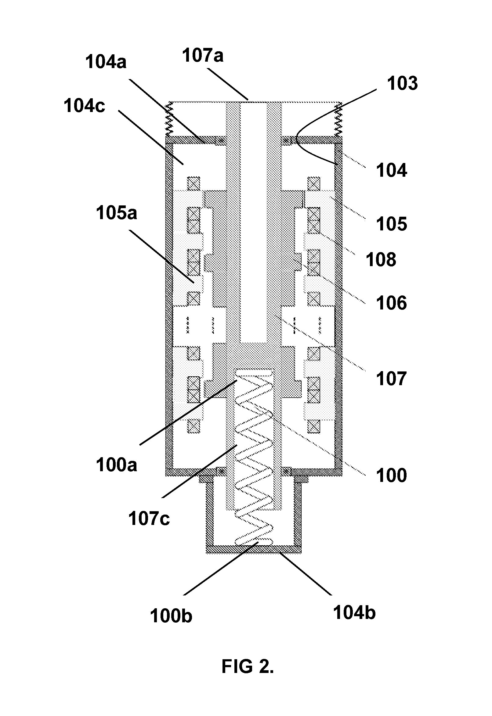
[0095]Preferred embodiments of the present invention will now be described with reference to FIGS. 1 to 18. The preferred embodiments include an electromagnetic active suspension unit which is suitable for use in providing active suspension in a vehicle. It would be readily understood by a person skilled in the art that alternative embodiments of the present invention may be suitably configured for use in other applications.

[0096]The electromagnetic active suspension unit includes a passive suspension element (100) adapted for operation in combination with an active suspension element (101). The passive suspension element (100) is configured for applying a passive force to a sprung mass of the vehicle and for absorbing vertical motion energy of the vehicle as a wheel of the vehicle traverses irregularities (e.g. sunken and raised sections) in a ground surface. The active suspension element (101) is configured to apply an active force to a sprung mass of the vehicle to alleviate unco...


PUM


Abstract

An active suspension system suitable for use with a vehicle, includes a passive suspension element with a first end adapted for rigid engagement to a sprung mass of the vehicle and a second end adapted for rigid engagement to an unsprung mass of the vehicle. Also included is an active suspension element with a linear switched reluctance actuator which has a first end adapted for rigid engagement to the sprung mass of the vehicle and a second end adapted for rigid engagement to the unsprung mass of the vehicle.

Description

TECHNICAL FIELD[0001]The present invention relates to the field of suspension systems and methods.BACKGROUND OF THE INVENTION[0002]Vehicle suspension systems are designed to absorb or isolate the passenger-carrying body of the vehicle from road shocks arising from irregularities in the road and to provide continuous contact between the wheels of the vehicle and the road in order to maximize passenger comfort, safety and road handling.[0003]Passive suspension systems consisting of mechanical springs and dampers often fail to meet the above objectives due to the tendency of mechanical springs being either too hard or too soft resulting in insufficient or excessive movement of the passenger-carrying compartment respectively in response to road shocks. Passive suspension systems also cannot produce active forces rapidly to absorb road shocks and therefore undesirable pitch and roll motions of the passenger-carrying compartment cannot be properly suppressed.[0004]Active suspension system...

Claims


Application Information

Patent Timeline
Patent Type & Authority Applications(United States)
IPC IPC(8): B60G11/14B60G11/00
CPCB60G11/14F16F15/022F16F15/03B60G2300/60B60G13/18B60G2300/50B60G13/14
Inventor CHENG, KA WAI ERICXUE, XIANGDANGZHANG, ZHU
Owner HONG KONG PRODUCTIVITY COUNCIL
Why Eureka
Try Eureka