Method and circuit assembly for the diagnosis of a load path in a vehicle

a load path and circuit technology, applied in the direction of continuity testing, short-circuit testing, instruments, etc., can solve the problem of not being able to use static diagnosis cases, and achieve the effect of being implemented easily and quickly

Active Publication Date: 2013-06-27
ROBERT BOSCH GMBH
View PDF5 Cites 15 Cited by
  • Summary
  • Abstract
  • Description
  • Claims
  • Application Information

AI Technical Summary

Benefits of technology

[0003]By contrast, the method according to the invention for diagnosis on a load path in a vehicle has the advantage that during the diagnosis a switchable test current having a defined level is produced and is output to the switchable load via a test switch at an output connection on the basis of a test control signal, wherein a resultant voltage at the output connection is sensed, conditioned and evaluated, wherein the load switch is opened during the diagnosis, and wherein the test control signal and the resultant switching state of the test switch are used to produce at least two different diagnosis cases. The load path comprises a DC voltage source, a switchable load that is permanently connected to a negative pole and a load switch that is permanently connected to a positive pole and that can be controlled by means of a load control signal, wherein in the closed state of the load switch a load current is carried by the switchable load. The method according to the invention can be implemented easily and quickly particularly in an electrical controller having a microprocessor.

Problems solved by technology

However, it is not possible to use the static diagnosis cases to distinguish between a short between the output connection and the negative pole of the DC voltage source and a nominal load in the case of such an inductive load having a low nonreactive resistance.

Method used


Image

  • Method and circuit assembly for the diagnosis of a load path in a vehicle
  • Method and circuit assembly for the diagnosis of a load path in a vehicle
  • Method and circuit assembly for the diagnosis of a load path in a vehicle

Examples


Embodiment Construction

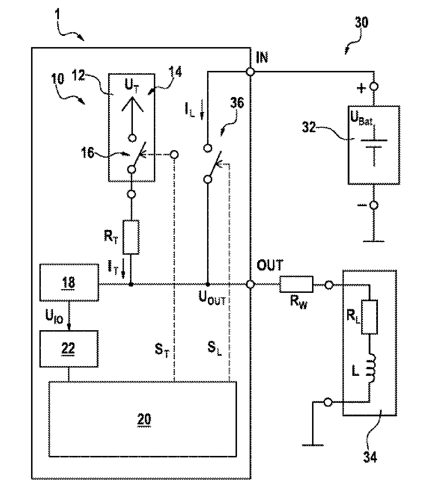
[0025]As can be seen from FIG. 1, a load path 30 in a vehicle comprises a DC voltage source 32, a switchable load 34 that is permanently connected to a negative pole (−) of the DC voltage source 32 and a load switch 36 that is permanently connected to a positive pole (+) of the DC voltage source 32 and that is arranged within an electronic controller 1 between an input connection IN and an output connection OUT and can be controlled by means of a load control signal SL which is produced and output by an evaluation and control unit 20 in the electronic controller 1. In the closed state of the load switch 36, a load current IL can be carried by the switchable load 34. In the exemplary embodiment shown, the switchable load 34 is as an equivalent circuit for an inductive load, such as an electrical relay coil, a solenoid valve, an electric motor, etc., with an ideal inductance L, which is higher than 100 μH, and a low nonreactive resistance RL, which is lower than 10Ω. The resistance RW...


PUM


Abstract

A method and circuit assembly for the diagnosis of a load path in a vehicle. The load path comprises a DC voltage source, a switchable load permanently connected to a negative pole and a load switch permanently connected to a positive pole, controlled by a load control signal, wherein in the closed state of the load switch a load current can be conducted through the switchable load (34). During diagnosis a test current having a defined level is generated and is output to the switchable load in accordance with a test control signal via a test switch on an output terminal, wherein a resulting voltage is detected, processed and evaluated at the output terminal, wherein the load switch (36) is opened during the diagnosis, and wherein at least two different diagnostic cases are generated via the test control signal and the resulting switching state of the test switch.

Description

BACKGROUND OF THE INVENTION[0001]The invention is based on a method for diagnosis on a load path in a vehicle and on a circuit arrangement for diagnosis on a load.[0002]Electronic controllers are known generally for controlling a wide variety of functions and devices and are increasingly being used in the automotive sector for the purpose of controlling a wide variety of functions and / or applications in a motor vehicle. An important class of such functions and / or applications has what are known as “low-side load circuits”, wherein a first connection of such load circuits is permanently connected to a negative pole of a vehicle battery or to the vehicle bodywork and a second connection of the load circuits is switched by an electronic controller. By way of example, the load circuits comprise solenoid valves, electromechanical relays, electric motors, etc. Typically, these load circuits are switched by means of a load switch, which is also called “high-side switch”, the first connecti...

Claims


Application Information

Patent Timeline
Patent Type & Authority Applications(United States)
IPC IPC(8): G01R31/02
CPCG01R31/025G01R31/006G01R31/52G01R31/54
Inventor SZOKE, SZILARDKOSZNAI, ZOLTANFATER, ISTVAN
Owner ROBERT BOSCH GMBH
Why Eureka
Try Eureka