Method and facility for cutting concrete product

a technology of concrete product and cutting method, which is applied in the direction of auxillary shaping apparatus, stone-like material working apparatus, ceramic shaping apparatus, etc., can solve the problems of decelerating the cutting process and affecting the cutting effect, and achieves the effect of enhancing the water jet cutting procedur

Inactive Publication Date: 2018-07-17
ELEMATIC
View PDF12 Cites 1 Cited by
  • Summary
  • Abstract
  • Description
  • Claims
  • Application Information

AI Technical Summary

Benefits of technology

[0011]Since the formed depressions or grooves extend to the area of the hollow-cores of the concrete product, the water jet only needs to cut the lower portion of the cured hollow-core concrete product without any open areas, which significantly speeds up the cutting process. Further, the formation of the depressions or grooves is easily and quickly implemented to the fresh uncured hollow-core concrete product, when compared to a cured concrete product.
[0014]In the method of an embodiment of the invention, the formed depressions or grooves in the concrete hollow-core product are preferably large enough to contain the nozzle of the water jet cutting device. This allows taking the nozzle close to the surface to be cut, which makes the water jet cutting process more efficient.
[0016]When the water jet cutting is implemented at a separate workstation, the cured hollow-core concrete product may be turned over, which allows the water jet cutting from the opposite side of the hollow-core concrete product from the forming of the depressions or grooves. This level surface enhances further the water jet cutting procedure.

Problems solved by technology

The sawing of a fresh, green element is also possible, but in that case the element to be sawed cannot contain reinforcing wires, or the sawing needs to be restricted in the areas not containing the reinforcing wires, because in a fresh element, the reinforcing wires would be detached from the cast element owing to their degree of prestressing, and this would lead to destructive results for the element.
Water jet cutting with abrasive water jet has also been experimented for cutting cured slipform cast products, but this is problematic for hollow-core slabs, since the hollow-core areas tends to break up the water jet and thus greatly decelerate the cutting process.

Method used


Image

  • Method and facility for cutting concrete product
  • Method and facility for cutting concrete product
  • Method and facility for cutting concrete product

Examples


Embodiment Construction

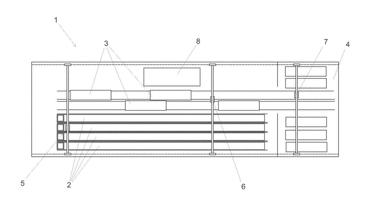
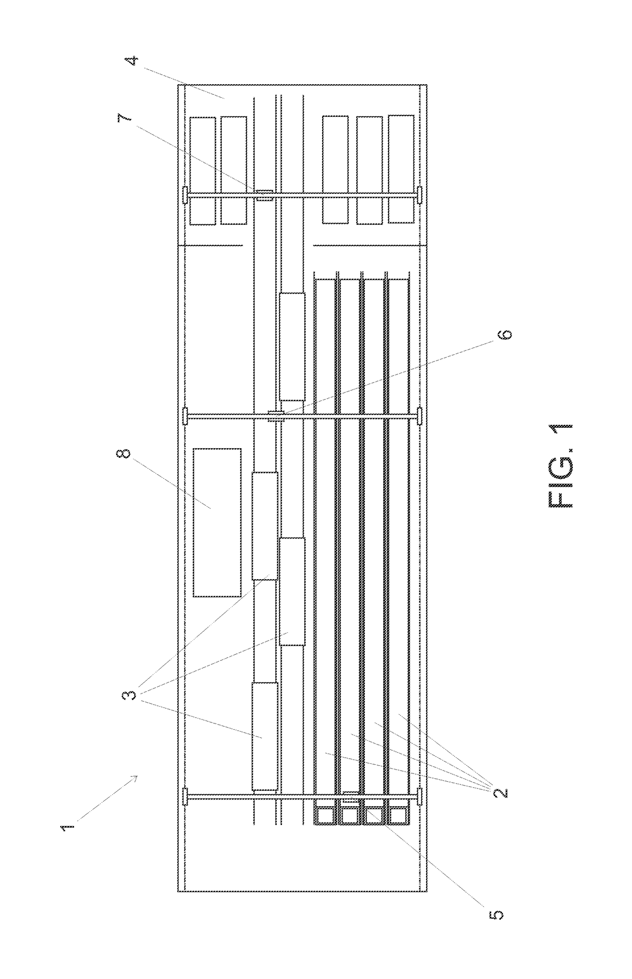
[0031]The manufacturing facility 1 for casting and cutting slipform cast hollow-core concrete products shown in FIG. 1 comprises a plurality of slipform casting beds 2, a plurality of transfer beds 3 for moving cut hollow-core concrete products to a storage area, a storage area 4, bridge cranes 5, 6, 7 for lifting and transferring cast concrete products and casting equipment, and water jet cutting station 8.

[0032]In the embodiment of FIG. 1, the slipform cast hollow-core concrete products are first cast as continuous slipform casting on the casting bed 2. After the casting, or during the casting process, depressions and / or grooves are formed on the top surface of the hollow-core concrete product at the predefined locations where lead-throughs or parts need to be cut away, or where other cuttings needs to be made.

[0033]The depressions and / or grooves are formed on the top surface of the fresh cast concrete product preferably with a separate slab processing machine moving on the same r...


PUM

PropertyMeasurementUnit
sizeaaaaaaaaaa
widthaaaaaaaaaa
pressureaaaaaaaaaa

Abstract

Method and facility or apparatus for cutting a slipform cast hollow-core concrete product with water jet cutting, wherein in the outer surface of the fresh cast hollow-core concrete product is formed depressions or grooves in the areas to be cut with water jet cutting before curing of the hollow-core concrete product, which depressions or grooves extend in the area of the hollow-cores of the concrete product.

Description

[0001]This application claims benefit of Finnish Patent Application No. 20145371, filed 22 Apr. 2014, the entire content of which is incorporated by reference herein for all purposes.BACKGROUND[0002]1. Field[0003]The present disclosure relates to cutting of prefabricated concrete products. More precisely the present disclosure relates to a method and an apparatus for cutting cured slipform cast hollow-core concrete products with water jet cutting.[0004]2. Description of Related Art[0005]Prefabricated concrete elements, such as hollow-core slabs and solid concrete slabs, are conventionally cast by slipform casting on long casting beds as a continuous casting process. The length of said continuous casting process is defined either on the basis of the total length of the elements to be cast, or on the basis of the maximum length of the casting bed. The length of casting beds used in slipform casting can be up to 150-200 m, depending on the size of the element plant. When a slipform cas...

Claims


Application Information

Patent Timeline
Patent Type & Authority Patents(United States)
IPC IPC(8): B24B1/00B26D3/08B28B11/12B28B17/00B24C1/04B28B11/08B28B11/16B26F3/00B28B1/08
CPCB28B11/0863B28B11/12B28B11/16B26F3/004B28B17/0036B24C1/045B26D3/08B28B1/084B28B11/14B28D1/22
Inventor KANKKUNEN, HEIKKI
Owner ELEMATIC
Why Eureka
Try Eureka