Optical leveling instrument with central common point consolidation structure

a technology of consolidation structure and leveling instrument, which is applied in the direction of instruments, height/levelling measurement, surveying and navigation, etc., can solve the problems of difficult to achieve a balanced state and difficulty in fixing the horizontal height, and achieve the effect of convenient storag

Inactive Publication Date: 2013-07-04
PENG KE OU +1
View PDF13 Cites 11 Cited by
  • Summary
  • Abstract
  • Description
  • Claims
  • Application Information

AI Technical Summary

Benefits of technology

[0007]A primarily objective of the present invention lies in an optical leveling instrument with central common point consolidation structure, which provides an optical leveling instrument able to prevent height difference from occurring in the emitted plane directional light beams during the stopping process, and is able to rapidly balance the directions. Intersection of two axes on the same plane and at equal height positions of a universal toggle support is used to form a central common point of center of rotation. In addition, the center of plane directional light also meets at the position of the central common point, thereby enabling rapid balancing and preventing intense variation in the amplitudes of oscillation of directional light during the stopping process. Another objective of the present invention lies in the stimulated directional light being provided with a horizontal and vertical directive function.
[0012]A seventh objective of the present invention lies in the waist portion of the swinging rod being fitted with a retaining device corresponding to the waist portion of a pedestal, and the retaining device produces a scissor pressure which acts radially on the swinging rod. The retaining device comprises a driving arm and a driven arm, and actuating one of the arms changes the scissor angle, moreover storing away is facilitated.

Problems solved by technology

Such displacements cause difficulties in fixing position of the horizontal height and fixing left-right position of the vertical line during use.
Because a radius length is provided between the toggle support device 101 and the laser transmitting unit 103, thus, the variation in angular position produced after the leveling instrument has been stopped makes it relatively difficult to achieve a balanced state.

Method used


Image

  • Optical leveling instrument with central common point consolidation structure
  • Optical leveling instrument with central common point consolidation structure
  • Optical leveling instrument with central common point consolidation structure

Examples


Embodiment Construction

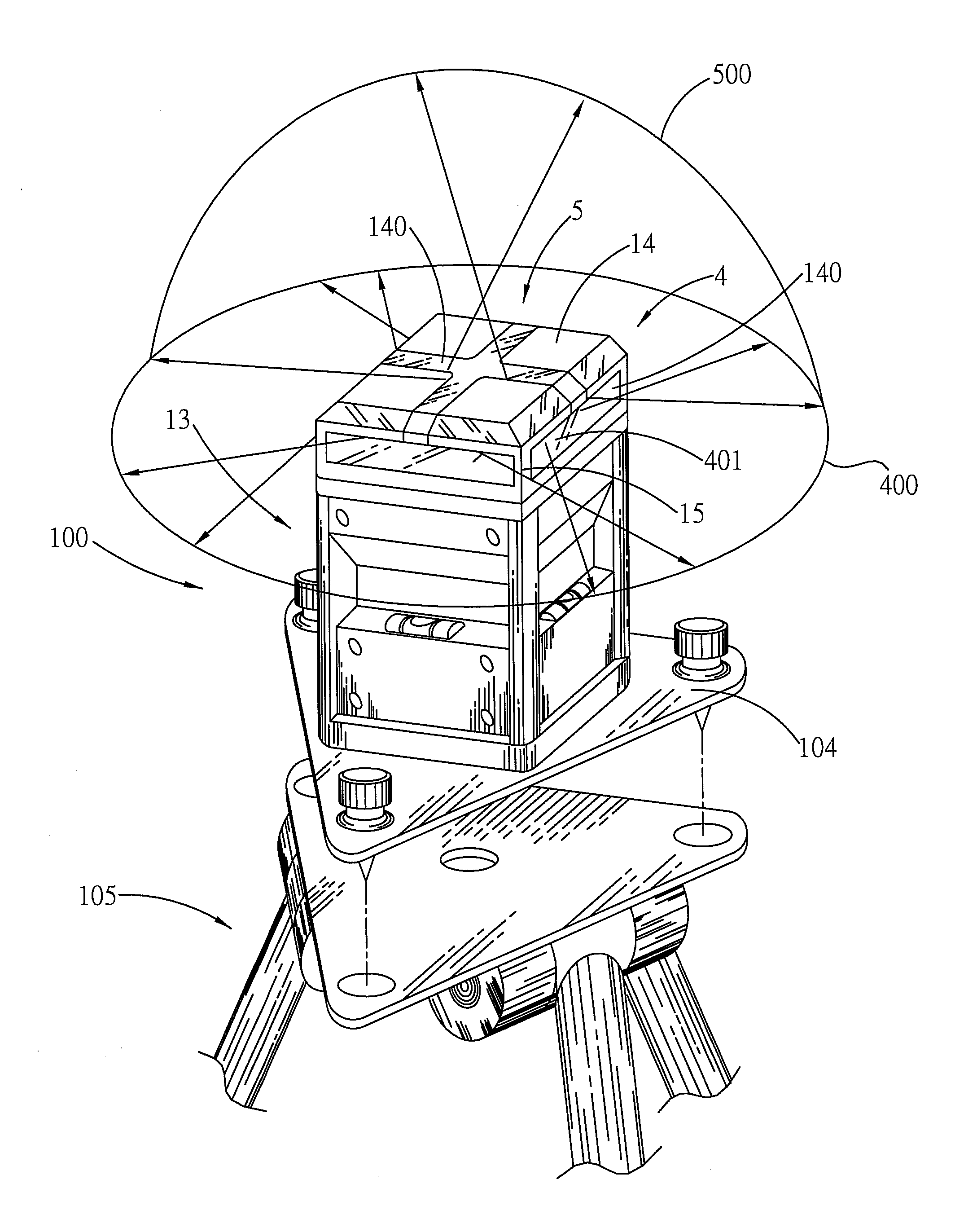
[0025]The present invention provides an optical leveling instrument, in which rotation within the interior of the system is based around a central common point serving as the center, and rapidly balancing of directional light beams is achieved through a consolidated common center point design.

[0026]Through the common center point of center of rotation, an optical plane surface of the present invention enables the height of the horizontal plane center of horizontal thin directional light to be consistent with the height of the balance position, thereby simplifying height adjustment of the leveling instrument. The present invention maintains the height of the horizontal thin directional light height, as well as ensuring there is no displacement during the stopping process of the vertical thin directional light.

[0027]A general semiconductor laser contains a ferromagnetic component, and generally uses a movement weight to cut and open the magnetic lines of force produced by permanent ma...


PUM


Abstract

The present invention provides an optical leveling instrument with central common point consolidation structure, and more particularly the center of working indicator light beams meet at the center of rotation point of two axes of toggle movement to serve as a central common point of center of rotation. During the stopping process, no height difference occurs in the directional light beams emitted by the instrument. The optical leveling instrument comprises a universal toggle support, and two horizontal working axes thereof intersect in the same plane and serves as the central common point of center of rotation. Moreover, centers of directional light beams emitted by a set of light emitting modules to collectively form the central common point of center of rotation.

Description

BACKGROUND OF THE INVENTION[0001](a) Field of the Invention[0002]An optical leveling instrument with central common point consolidation structure, which provides an optical leveling instrument able to prevent a height difference from occurring in the emitted plane directional light beams during the stopping process, and is able to rapidly balance the directions.[0003](b) Description of the Prior Art[0004]Horizontal thin directional light and toggle support device of the movement weight mechanism of current common leveling instruments are not in plane. During the process of stopping swinging, variations in the height of the horizontal thin directional light for directional leveling (as depicted in FIGS. 1 and 2) occur. Similarly, during the process of stopping swinging, transverse displacement will occur in the vertical thin directional light. Such displacements cause difficulties in fixing position of the horizontal height and fixing left-right position of the vertical line during u...

Claims


Application Information

Patent Timeline
Patent Type & Authority Applications(United States)
IPC IPC(8): G01C5/00
CPCG01C15/004
Inventor PENG, KE-OU
Owner PENG KE OU
Why Eureka
Try Eureka