Car Wash Air Dryer Blower Flow Restrictor Arrangement And Method

a technology for restricting the flow of air dryers and air dryers, which is applied in the direction of vehicle cleaning, cleaning using liquids, lighting and heating apparatuses, etc. it can solve the problems of large electric power consumption, noisy high-volume air blowers, and low airflow output, so as to minimize power consumption and noise, the effect of greatly reducing the load on the blower motor

Inactive Publication Date: 2013-07-04
PECO CORP
View PDF10 Cites 9 Cited by
  • Summary
  • Abstract
  • Description
  • Claims
  • Application Information

AI Technical Summary

Benefits of technology

[0016]In the closed position, the load on the blower motor is greatly reduced by preventing air from being drawn into the impeller to minimize power consumption and noise in a st...

Problems solved by technology

The high volume air blowers are quite noisy when operating and consume considerable electric power when running at full capacity so that various arrangements have been devised to reduce the airflow output of the blowers when cars are not present in the drying zone.
Such an arrangement is bulky and complicated particularly since it must accommodate a safety mesh which usually also installed over the inlet to prevent objects from entering the blower plenum a person from reaching into the blower interior which could result in an injury.
Also, the air flow may be restricted to some extent by the pressure of the damper plates even when th...

Method used


Image

  • Car Wash Air Dryer Blower Flow Restrictor Arrangement And Method
  • Car Wash Air Dryer Blower Flow Restrictor Arrangement And Method
  • Car Wash Air Dryer Blower Flow Restrictor Arrangement And Method

Examples


Embodiment Construction

[0027]In the following detailed description, certain specific terminology will be employed for the sake of clarity and a particular embodiment described in accordance with the requirements of 35 USC 112, but it is to be understood that the same is not intended to be limiting and should not be so construed inasmuch as the invention is capable of taking many forms and variations within the scope of the appended claims.

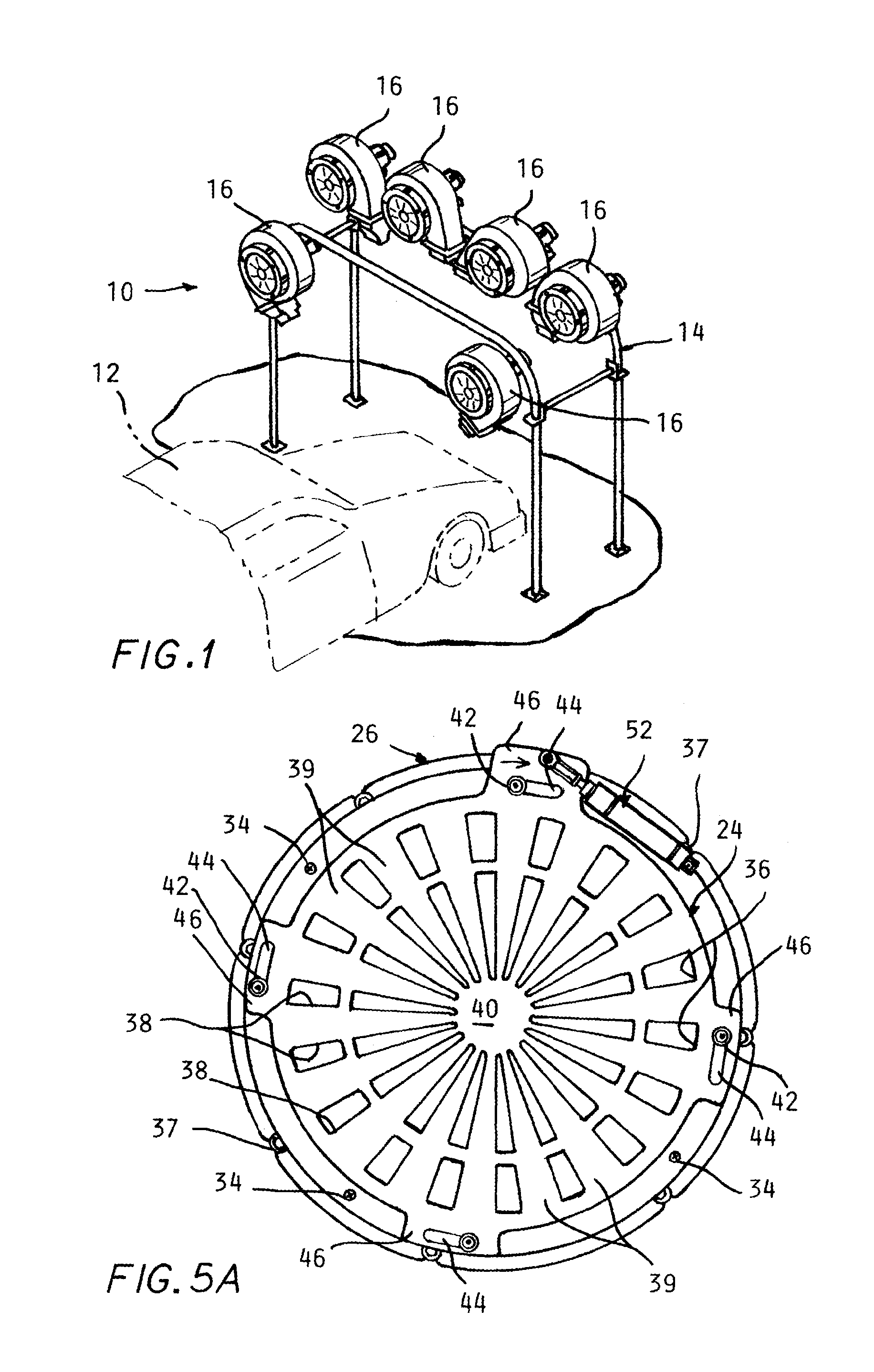
[0028]Referring to the drawings, FIG. 1 shows the dryer zone 10 of a typical car wash system. A car 12 depicted in fragmentary form is transported into the zone by a conveyor engaging the vehicle tires in the well known manner.

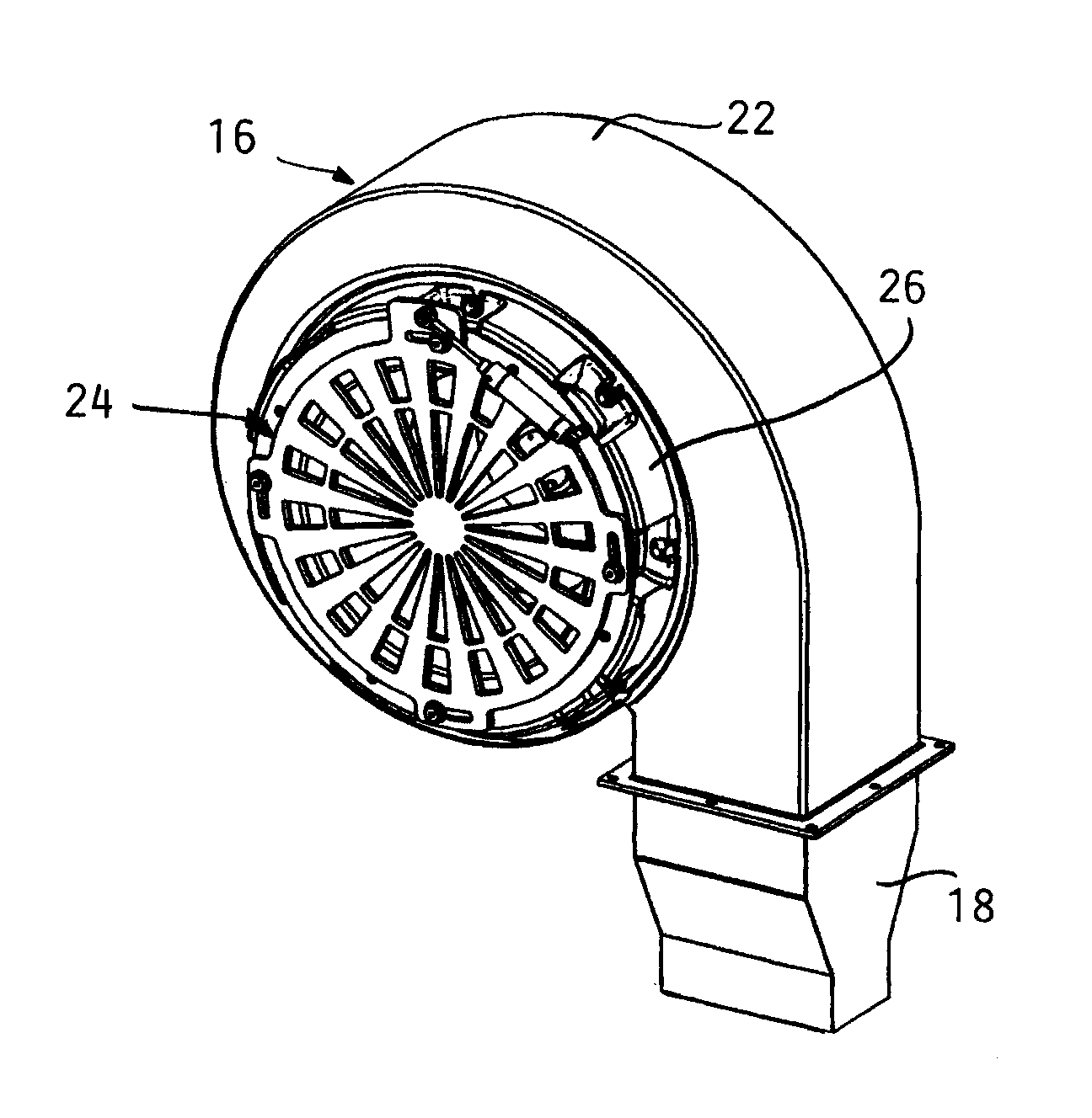
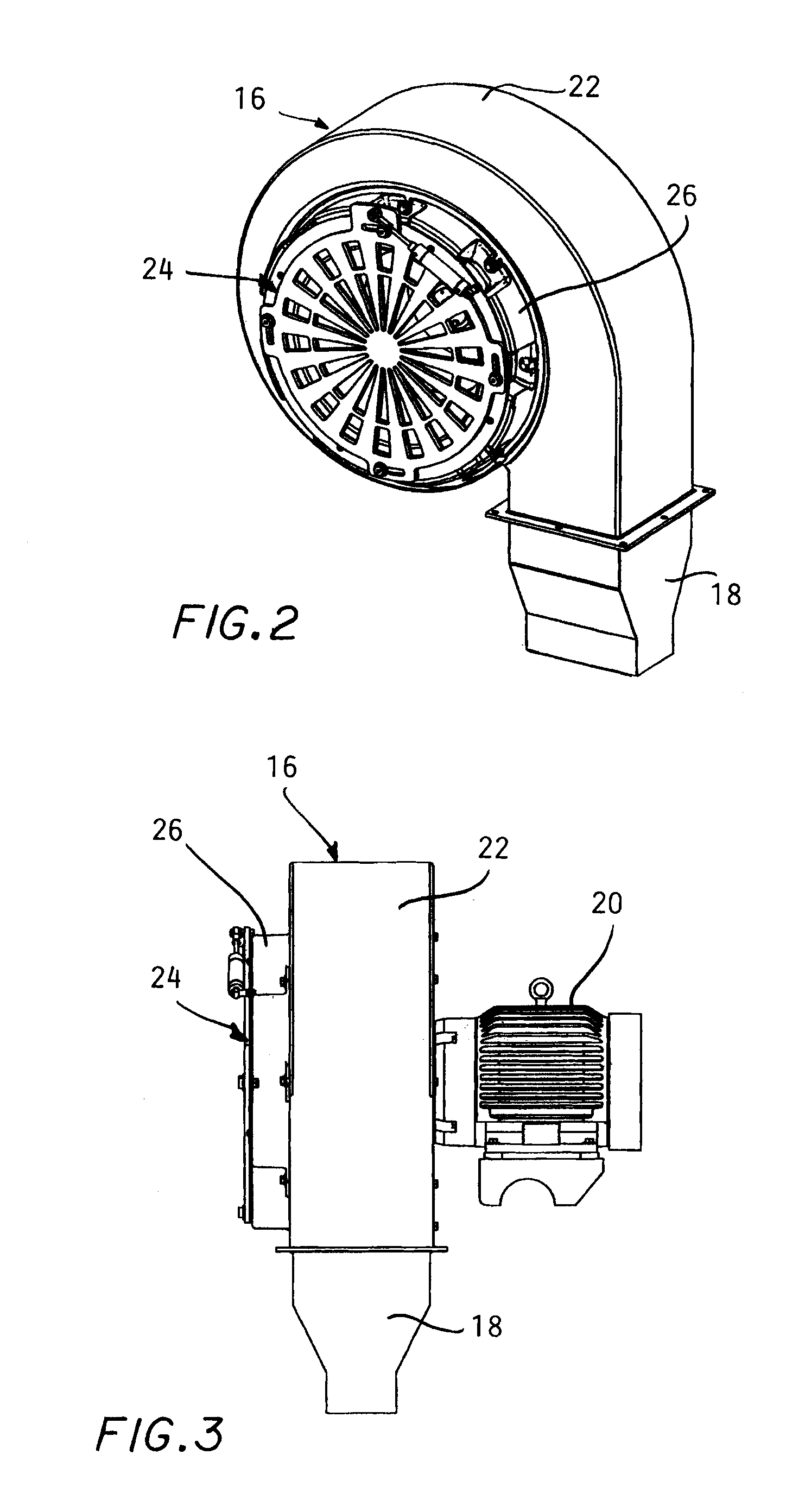
[0029]A framework 14 through which the car can pass has an overhead array of high volume blowers 16 mounted thereon. The blowers or fans are typically of a centrifugal design with well know squirrel cage impeller. Each blower 16 has a nozzle outlet 18 directing a powerful stream of air at the washed vehicle to blow off rinse water and dry the car, ...


PUM


Abstract

Stacked inner and outer discs are mounted over an air blower inlet opening of each blower in a car wash system drying zone with matched sets of radial slots and spokes formed in each disc. An actuator rotates one disc between positions in which the set of slots in one disc is aligned with the set of slots in the other disc to allow air flow into the blower inlet to dry a car in the dryer zone to a position in which the set of spokes overlie the set of slots in the other disc to thereby block inlet air flow to reduce the load on a blower motor when a car is not in the dryer zone.

Description

CROSS REFERENCE TO RELATED PATENT APPLICATIONS[0001]This application claims the benefit of U.S. provisional application No. 61 / 526,788 filed on Aug. 24, 2011.BACKGROUND OF THE INVENTION[0002]This invention concerns car wash systems and more particularly blowers for the drying zone of such systems.[0003]In a car wash system, an array of high volume air blowers is typically mounted on a framework within which a car which has been washed is transported on a conveyor with nozzles directing air jets of the car so as to blow off the rinse water and dry the surfaces of the car.[0004]The high volume air blowers are quite noisy when operating and consume considerable electric power when running at full capacity so that various arrangements have been devised to reduce the airflow output of the blowers when cars are not present in the drying zone.[0005]These arrangements have included pivoted damper plates which are installed at the blower inlet (or the outlet) of the blower. Such an arrangeme...

Claims


Application Information

Patent Timeline
IPC IPC(8): B60S3/00
CPCB60S3/002F26B2210/12F26B21/001
Inventor JONES, MARK T.
Owner PECO CORP
Why Eureka
Try Eureka