Method and System for Reducing the Visibility of a Plume Created at the Outlet of an Industrial Process

a technology of industrial process and outlet, which is applied in the direction of gas/liquid distribution and storage, mixing machines, lighting and heating equipment, etc., can solve the problems of unsatisfactory visibility of visible plumes, poor visibility, accessibility problems, etc., and achieve the effect of reducing the visibility of a plum

Inactive Publication Date: 2013-07-04
BRUNNSCHWEILER
View PDF3 Cites 4 Cited by
  • Summary
  • Abstract
  • Description
  • Claims
  • Application Information

AI Technical Summary

Benefits of technology

[0012]The invention provides a method and system for reducing the visibility of a plume created at the outlet of an industrial process, which industrial process expels hot, humid air into the outside air through an outlet and where, as a result of the expelled air coming into contact with the outside air, a visible plume might otherwise be created. A method according to the invention includes the...

Problems solved by technology

Visible plumes are undesirable for several reasons.
On the one hand, they are unsightly and they are perceived by the population as a sign of pollution because they look like a column of smoke.
On the other hand, if the temperature outside the chimney is very low, the drops of water condensed on leaving the chimney and coming into contact with the outside air can freeze, thus causing the plume to behave like a snow cannon, which might even cause safety problems (poor visibility, accessibility problems, etc.).
This chamber is sometimes located in the suction section of the process extraction fan itself, which adds the need for the fan to be excessively oversized.
Other times, the chamber is located in the impell...

Method used


Image

  • Method and System for Reducing the Visibility of a Plume Created at the Outlet of an Industrial Process
  • Method and System for Reducing the Visibility of a Plume Created at the Outlet of an Industrial Process
  • Method and System for Reducing the Visibility of a Plume Created at the Outlet of an Industrial Process

Examples


Embodiment Construction

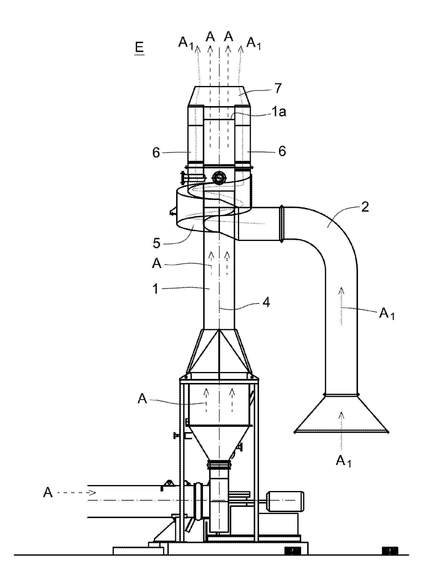
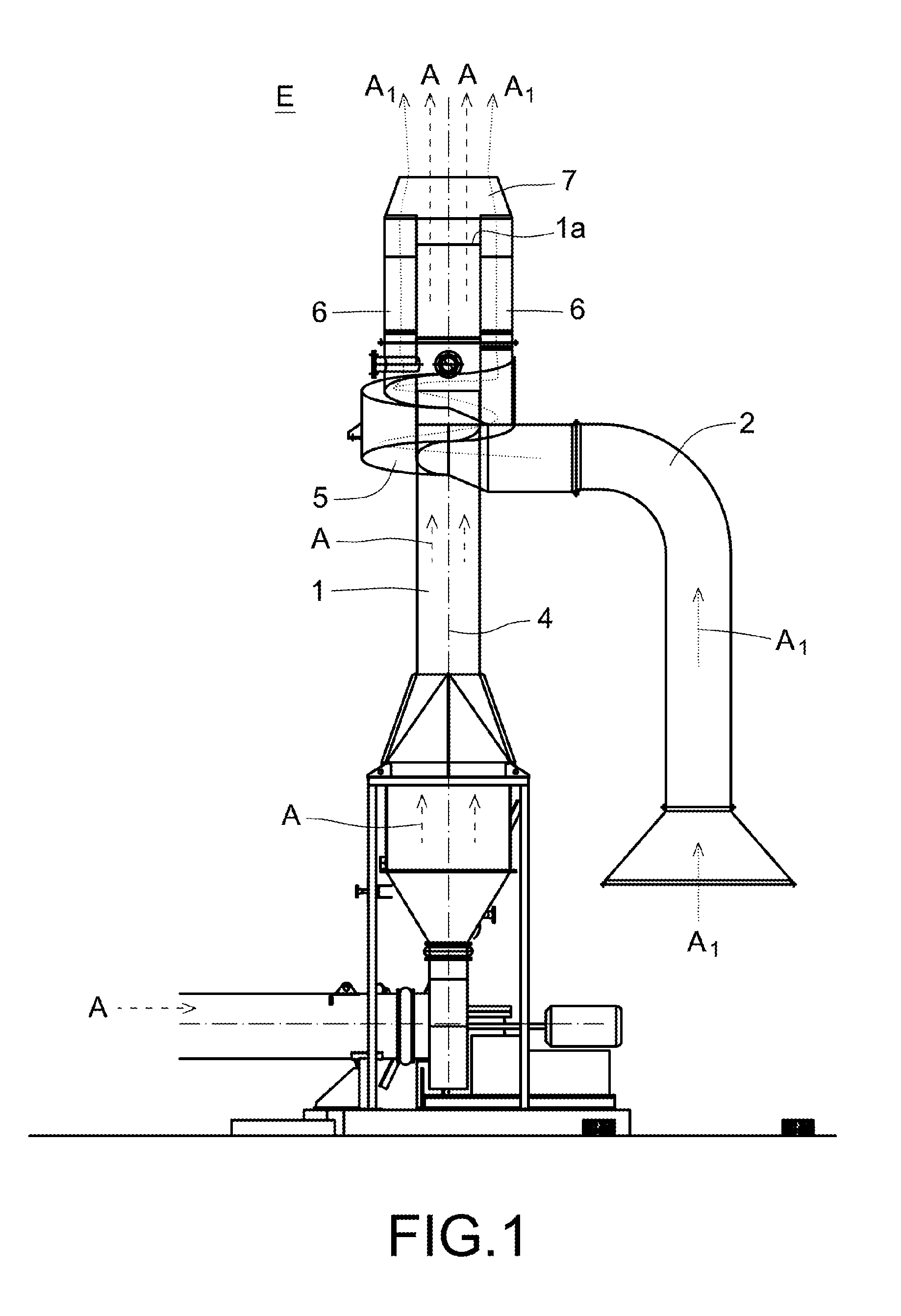
[0021]Embodiments of the invention provide a method and corresponding apparatus for reducing the visibility of a plume created at the outlet of an industrial process, where the industrial process expels hot, humid air A into the outside air E through an outlet 1 and, as a result of the expelled air coming into contact with the outside air, a visible plume might otherwise be created.

[0022]FIG. 1 shows a diagram of a first embodiment of a system according to the invention, which performs the steps of a method according to the invention. This system includes, as a main item, an outlet 1 provided with an output area 1a to allow for the expulsion of the hot, humid air A into the outside atmosphere (which comprises outside air E). The hot, humid air A from the industrial process has been represented using dashed lines. The outlet 1 shown in FIG. 1 is a chimney, although it could also take other forms, for example, any diffuser, a vertical or horizontal air accelerator outlet, or a high sp...


PUM

PropertyMeasurementUnit
Flow rateaaaaaaaaaa
Speedaaaaaaaaaa
Areaaaaaaaaaaa

Abstract

A method and system for reducing the visibility of a plume created at the outlet of an industrial process, where the industrial process expels hot, humid air into the outside air through an output area of an outlet and, as a result of the expelled air A coming into contact with the outside air E, a visible plume might otherwise be created. The method includes the steps of having an auxiliary air that is dryer than the process air and hotter than the outside air available and combining this auxiliary air with the hot, humid process air such that the auxiliary air forms a protective, insulating or sheathing layer of air around the process air. This combination of the process air with the auxiliary are is carried out after (i.e., downstream from) an extraction process or processes of the industrial process and in the atmosphere generally adjacent to the output area of the process outlet.

Description

CROSS-REFERENCE TO RELATED APPLICATION[0001]This application claims priority to European Patent Application No. 11380108, filed Dec. 29, 2011. The contents of that application are incorporated by reference in their entirety.BACKGROUND OF THE INVENTION[0002]1. Field of the Invention[0003]The invention relates to a method and system for reducing the visibility of a plume created at the outlet of an industrial process, which to date is usually visible at the chimney outlet or other outlet of the industrial process.[0004]2. Description of Related Art[0005]Certain types of industrial facilities, such as paper drying plants, generate large amounts of very hot, humid waste air, i.e. very hot air loaded with a great mass of water vapor. This air, usually called “exhaust” air, is emitted directly into the atmosphere, producing some important negative effects, among which is the effect known as a visible “plume”. The visible plume is a very high column of what looks like white smoke, which is...

Claims


Application Information

Patent Timeline
IPC IPC(8): F17D1/16B01F23/10
CPCF17D1/16B01F5/0057F26B25/005B01F3/02Y10T137/2076Y10T137/0391B01F23/10B01F25/10
Inventor LOPEZ, OSCARLARREA, IRAIDE
Owner BRUNNSCHWEILER
Why Eureka
Try Eureka