
Ram air channel arrangement and aircraft air conditioning system

Inactive Publication Date: 2013-07-04
AIRBUS OPERATIONS GMBH
View PDF5 Cites 5 Cited by
  • Summary
  • Abstract
  • Description
  • Claims
  • Application Information

AI Technical Summary

Benefits of technology

The invention is a ram air channel arrangement for an aircraft that reduces turbulence and pressure losses in the flow of ram air through the heat exchanger. This is achieved by equipping the arrangement with a flow control device that regulates the flow of air. This results in improved cooling capacity of the heat exchanger and reduces the fuel consumption of the aircraft. The flow control device can be connected to the heat exchanger, making it easy to retrofit existing arrangements. The heat exchanger may be configured as a plate heat exchanger with multiple ram air outlet portions, each associated with a flow control device to ensure a low-turbulence flow. The flow control devices are connected to regions of the heat exchanger that separate two ram air inlet or outlet portions from another.

Problems solved by technology

In a ram air flow, which is conveyed through a heat exchanger disposed in a ram air channel, pressure losses occur particularly in the region of a ram air inlet of the heat exchanger as a result of the heat exchanger causing a narrowing of the cross section, through which the ram air flow may flow.
High pressure losses occur frequently if, for example as a result of restricted installation space, it is impossible to design the ram air channel in a way that enables a flow straight towards the ram air inlet of the heat exchanger, i.e. substantially at right angles to the cross-sectional area of flow of the heat exchanger ram air inlet.
This leads to a reduction of the ram-air volume rate of flow through the heat exchanger and hence to an undesirable reduction of the cooling capacity of the heat exchanger.

Method used


Image

  • Ram air channel arrangement and aircraft air conditioning system
  • Ram air channel arrangement and aircraft air conditioning system
  • Ram air channel arrangement and aircraft air conditioning system

Examples


Embodiment Construction

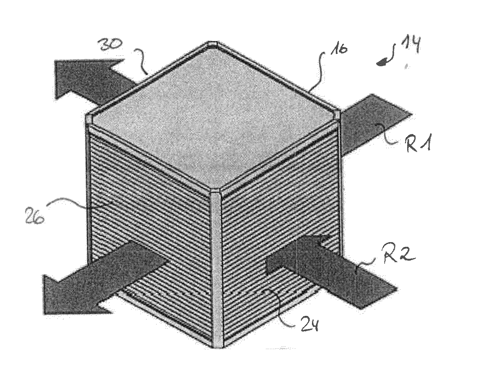
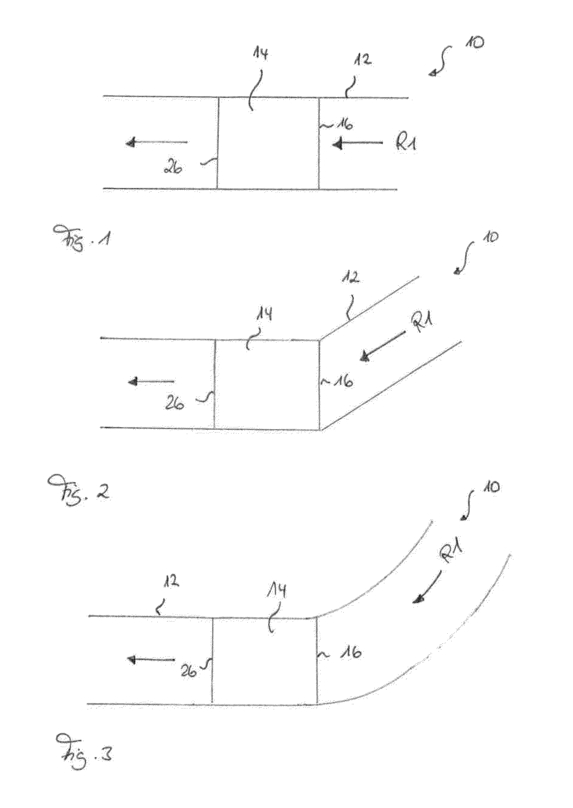
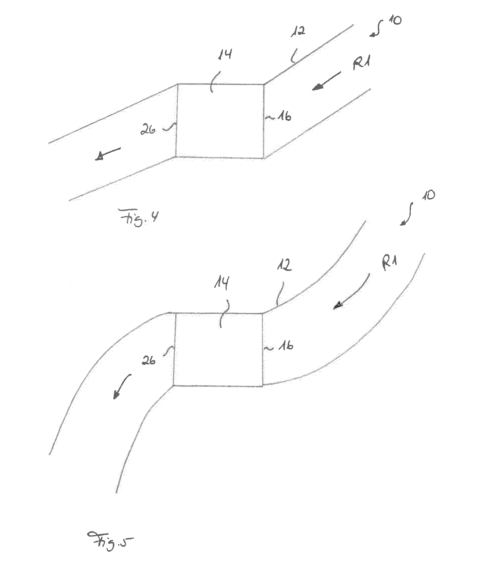
[0037]FIGS. 1 to 5 each show a ram air channel arrangement 10 having a ram air channel 12, through which ram air may flow in a direction R1. The ram air channel 12 has a ram air channel inlet, which is not represented in the figures, is disposed in the region of an aircraft skin and configured for example in the form of an NACA inlet, as well as a ram air channel is outlet that is formed likewise in the region of the aircraft skin. The ram air flow through the ram air channel 12 is controlled by appropriate positioning of one or more ram air channel inlet flaps and / or one or more ram air channel outlet flaps. While the aircraft is operating on the ground, the ambient air is conventionally fed through the ram air channel 12 by means of a suitable feed device, which is not shown in the figures. While the aircraft is flying, on the other hand, ambient air generally flows through the ram air channel 12 as a result of the pressure conditions in the region of the ram air channel inlet and...


PUM


Abstract

A ram air channel arrangement includes a ram air channel adapted to be flown through with ram air, a heat exchanger disposed in the ram air channel and including a ram air inlet for feeding the ram air flowing through the ram air channel into the heat exchanger and a ram air outlet for removing the ram air from the heat exchanger, and at least one flow control device having a cross section widening in the direction of the ram air inlet and positioned in the ram air channel upstream of the ram air inlet such that it guides the ram air flowing through the ram air channel in the direction of the ram air inlet and / or and at least one flow to control device having a cross section widening in the direction of the ram air outlet and positioned in the ram air channel downstream.

Description

CROSS REFERENCE TO RELATED APPLICATIONS[0001]This application claims the benefit of and priority to U.S. Patent Provisional Application No. 61 / 502,382, filed Jun. 29, 2011, and German Patent Application No. 10 2011 105 968.0 filed Jun. 29, 2011, the contents of each of which are hereby incorporated by reference in their entirety.TECHNICAL FIELD[0002]The present invention relates to a ram air channel arrangement and to an aircraft air conditioning system equipped with such a ram air channel arrangement.BACKGROUND OF RELATED ART[0003]Currently in commercial aircraft so-called air-assisted air conditioning systems are conventionally used to air condition the aircraft cabin. An aircraft air conditioning system is used to cool the aircraft cabin, which would otherwise become overheated as a result of heat loads, such as for example insolation, body heat of the passengers and waste heat from equipment on board the aircraft. The aircraft air conditioning system moreover feeds sufficient fr...

Claims


Application Information

Patent Timeline
IPC IPC(8): B64D13/06
CPCB64D13/00B64D13/06F28D2021/0021F28F9/0282F28D9/0062Y02T50/56Y02T50/50
Inventor SCHMID, MARTIN
Owner AIRBUS OPERATIONS GMBH
Learn More