Metal-to-metal sealing arrangement for control line and method of using same

a technology of sealing arrangement and control line, which is applied in the direction of drilling casings, drilling pipes, borehole/well accessories, etc., can solve the problems of complex exit arrangement, insufficient space available on most completions to incorporate this sealing, and difficulty in completion, etc., to achieve minimal height increase, reduce the effect of height impact and sufficient height and clearan

Active Publication Date: 2013-07-04
VETCO GRAY
View PDF4 Cites 16 Cited by
  • Summary
  • Abstract
  • Description
  • Claims
  • Application Information

AI Technical Summary

Benefits of technology

[0009]This arrangement on the wellhead of the control line assemblies advantageously provides sufficient height and clearance to allow for the installation of a plurality of control lines entering into the tubing hanger and exiting from the wellhead.
[0010]This invention provides several additional advantages. The invention advantageously overcomes the problem of bending and fitting multiple control lines in the limited space available by moving the exit point down to the main wellhead body and creates multiple control line entry points on the tubing hanger body with a minimal height increase. The multiple control lines can be accommodated in a “single band” around the tubing hanger and wellhead body thereby minimizing any height impact. In addition, safety for personnel is improved by this invention given that work around an open well, which may involve working underneath suspended BOP stacks, is minimized. From an operational safety standpoint, hydraulic control line communication can be advantageously achieved immediately after the tubing hanger has lan

Problems solved by technology

On conventional surface wellhead applications, however, there is insufficient space available on most completions to incorporate this sealing arrangement
However, large numbers of control lines make this conventional exit arrangement complex and difficult to complete within the limited space available in the wellhead upper bowl area.
Fitting multiple control lines in the limited space currently available is difficult and labor intensive, with control lines frequently

Method used


Image

  • Metal-to-metal sealing arrangement for control line and method of using same
  • Metal-to-metal sealing arrangement for control line and method of using same
  • Metal-to-metal sealing arrangement for control line and method of using same

Examples


Embodiment Construction

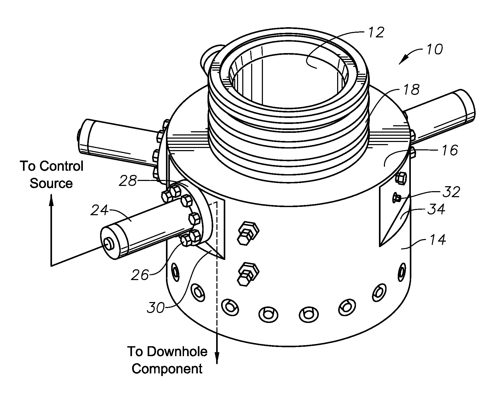
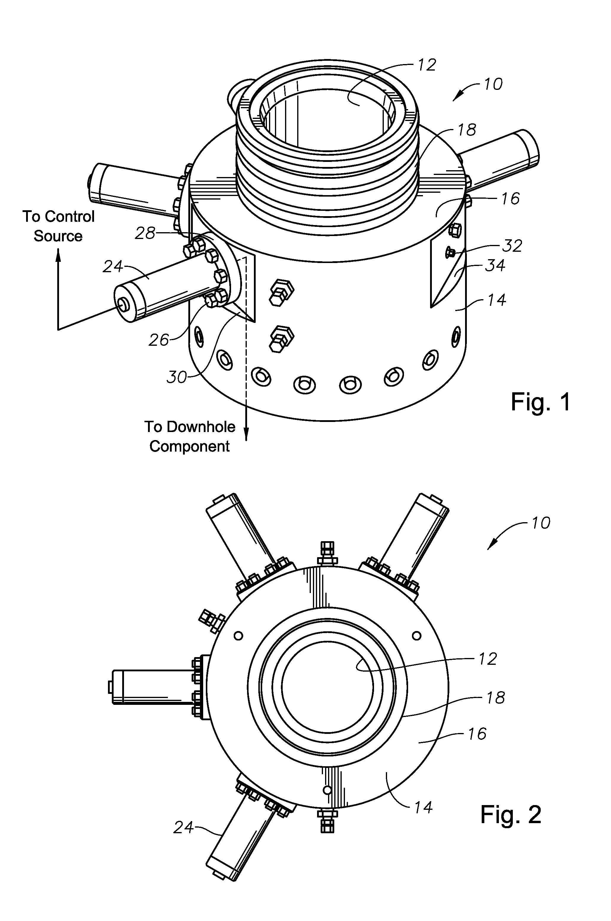
[0015]FIG. 1 shows a perspective view of an embodiment of a generally cylindrical wellhead 10 having a bore 12, that may be installed on a surface or subsea well. In this embodiment, the wellhead 10 further has a body or wellhead body 14 with a sidewall 16. The sidewall may have a radial thickness defined generally by a difference between an outer surface of the body 14 and an upper connection 18. The upper connection 18 shown has a generally cylindrical shape, although the upper connection can take the form of a flange, and extends upward from the body 14 of the wellhead 10.

[0016]Continuing to refer to FIG. 1 and also FIG. 2, a control line assembly 24, which may be one of a plurality of assemblies, is mounted to the body 14 of the wellhead 10 via bolts 26. The bolts 26 pass through bolt passages (not shown) in a flange 28 on a mounting end of the control line assembly 24 and further engage corresponding bolt passages (not shown) formed in the body 14 of the wellhead 10. The flange...


PUM


Abstract

A well completion system includes a wellhead, a control line assembly for use in completions that is mounted to the wellhead, and a tubing hanger. The control line assembly includes a cylinder, a main housing assembly, a passage and a metal-to-metal seal. A split lockout ring provides a positive lock to the passage. Control lines enter the tubing hanger and exit via the wellhead. This arrangement on the wellhead provides sufficient height and clearance to allow for the installation of a plurality of control lines.

Description

FIELD OF THE INVENTION[0001]This invention relates to oilfield completion systems and, in particular, to a wellhead completion system having a metal-to-metal sealing arrangement for control lines installed on a surface wellhead.BACKGROUND OF THE INVENTION[0002]For many surface and subsea oil and gas wells, a series of pipes, fittings, valves, and gauges are used on a wellhead to control the flow and achieve well completion. A Christmas or production tree is generally attached to the wellhead and the pipes, fittings, valves and gauges are typically routed and connected to the tree. One, or a plurality of, penetrators or stems, may be installed in a Christmas tree to engage components installed within the wellhead, such as a tubing hanger. The penetrators may be horizontal, vertical, or at other angles, and allow downhole control lines, such as electrical and / or hydraulic, to be routed through the tree and tubing hanger sidewalls and be routed down to components below the wellhead.[00...

Claims


Application Information

Patent Timeline
IPC IPC(8): E21B33/068
CPCE21B33/038E21B33/047E21B33/02E21B33/0387E21B33/03
Inventor SINNOTT, JAMES A.CHRISTIE, ARLANECAMPBELL, LAURA
Owner VETCO GRAY
Why Eureka
Try Eureka