Pumping station for a cooling and lubricating fluid containing particulate matter

a technology of lubricating fluid and pumping station, which is applied in the direction of broaching machines, grain treatment, manufacturing tools, etc., can solve the problems of high cost, complicated arrangement, and inability to reliably convey machining chips

Inactive Publication Date: 2000-10-03
MANN HUMMEL GMBH +1
View PDF9 Cites 31 Cited by
  • Summary
  • Abstract
  • Description
  • Claims
  • Application Information

AI Technical Summary

Problems solved by technology

In the above mentioned known pumping stations, it has been recognized as a disadvantage that either the reliable conveyance of machining chips can only be achieved with relatively low supply volume flows of the chips, or the collecting containers must have a relatively high total structural height to provide for a sufficiently steep slope of the walls and a sufficient collecting volume.
However, in view of the danger of polluting ground water resources in the event of any leakage, and thus as required by environmental protection regulations, the pumping stations arranged below floor level in this manner have required a double-walled collecting container securely anchored in a foundation constructed below the shop floor.
Such an arrangement is quite complicated and expensive.
Nonetheless, some chips become caught between the top surface of the container floor a

Method used


Image

  • Pumping station for a cooling and lubricating fluid containing particulate matter
  • Pumping station for a cooling and lubricating fluid containing particulate matter
  • Pumping station for a cooling and lubricating fluid containing particulate matter

Examples


Embodiment Construction

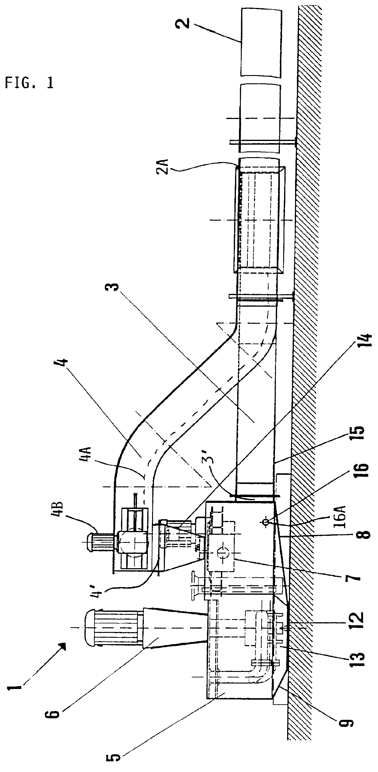
In a machining station, which is not shown, a chip-removing machining operation is being carried out while using a cooling and lubricating fluid. The removed chips are entrained in the flow of cooling and lubricating fluid, which flows from a transfer line or transfer station, which is not shown, through a supply line 2 to a pumping station 1. Interposed between the pumping station 1 and the supply line 2, and specifically connected to an inlet junction 2A a short distance before or upstream of the pumping station 1, are two branch lines 3 and 4.

A first branch line 3 is connected coaxially in line with the supply line 2, and both the supply line 2 and the first branch line 3 slope downward with a slight slope angle toward the pumping station 1, for example having a slope angle of less than 5.degree. or even less than 3.degree.. The proper slope angle for the supply line 2 is known in the art for ensuring proper flow of the fluid and chips. A second branch line 4 is connected to the ...


PUM

PropertyMeasurementUnit
Angleaaaaaaaaaa
Angleaaaaaaaaaa
Angleaaaaaaaaaa

Abstract

A pumping station for pumping a cooling and lubricating fluid containing particulate matter such as machining chips has a compact structure with a relatively low total structural height, while still assuring that the chips are conveyed with the fluid to the pump suction inlet, without settling-out or accumulating in the apparatus. The pumping station (1) includes a collecting container (5) with at least one pump (6) arranged therein, a chip breaker (7) and a supply conduit arrangement. The supply conduit arrangement includes a supply line (2) through which the cooling and lubricating fluid containing the machining chips is received from a machining tool or transfer station. Furthermore, two branch lines (3) and (4) are interposed and connected between the supply line (2) and the collecting container (5). A first branch line (3) conveys the fluid, from which the chips have been removed, with a slight downward slope toward the collecting container (5). The second branch line (4) conveys the chips that have been removed from the fluid flow. A scraper conveyor or the like conveys the chips upward through the second branch line (4), and the outlet end of the branch line (4) is arranged directly above the chip breaker (7), which in turn is arranged above the outlet end of the fluid conveying branch line (3). The comminuted chips thus fall from the breaker (7) directly into the flow of fluid, in which the chips are then entrained and carried along into the sump (13) of the collecting container (5), where the chips and fluid are sucked and pumped away by the pump (6).

Description

The invention relates to a pumping station for pumping a cooling and lubricating fluid that contains particulate matter such as chips, shavings, turnings, cutting dust, and the like from a machining operation.BACKGROUND INFORMATIONPumping stations of the above mentioned type are known in the art and generally have a supply line or conduit through which the cooling and lubricating fluid containing particulate matter is delivered, a collecting container connected to the supply line, and a pump communicating with the collecting container. A discharge line is connected to the pressure output side of the pump. Such generally known pumping stations are used in connection with machine tools, such as boring, cutting, or milling machines, for pumping away from the machine tools, for example through pipe conduits, the cooling and lubricating fluid that contains any chips or shavings arising during the chip-removal machining of workpieces. Separate equipment arranged at a separate location wil...

Claims


Application Information

Patent Timeline
IPC IPC(8): B23Q11/10B23Q11/00
CPCB23Q11/1069Y10T409/40175Y10T409/304088
Inventor FACHINGER, ALFONSJANSSEN, MARKWILDEN, STEFAN
Owner MANN HUMMEL GMBH
Why Eureka
Try Eureka