Collimator for a pixelated detector

a collimator and detector technology, applied in the field of collimator for collimating photons, can solve the problems of reducing detector efficiency, limiting the overall image quality and performance of resolution-sensitivity tradeoff, etc., and achieve the effect of reducing heigh

Inactive Publication Date: 2013-07-04
GE MEDICAL SYST ISRAEL
View PDF3 Cites 47 Cited by
  • Summary
  • Abstract
  • Description
  • Claims
  • Application Information

AI Technical Summary

Benefits of technology

[0011]In each of the various embodiments, the collimator has multiple groups of collimator holes registered with at least some of the detector pixels on a one-group-to-one-pixel (i.e., multiple-holes-per-pixel) basis, rather than simply one hole per pixel as is the case in prior art registered collimators. Each of the embodiments may further comprise an imaging equipment arrangement including a pixelated detector havi

Problems solved by technology

However, the resolution-sensitivity tradeoff remains a limitation on overall image quality and performance.
However, pixel size is a factory process standard which is difficult and costly to change, and ch

Method used


Image

  • Collimator for a pixelated detector
  • Collimator for a pixelated detector
  • Collimator for a pixelated detector

Examples


first embodiment

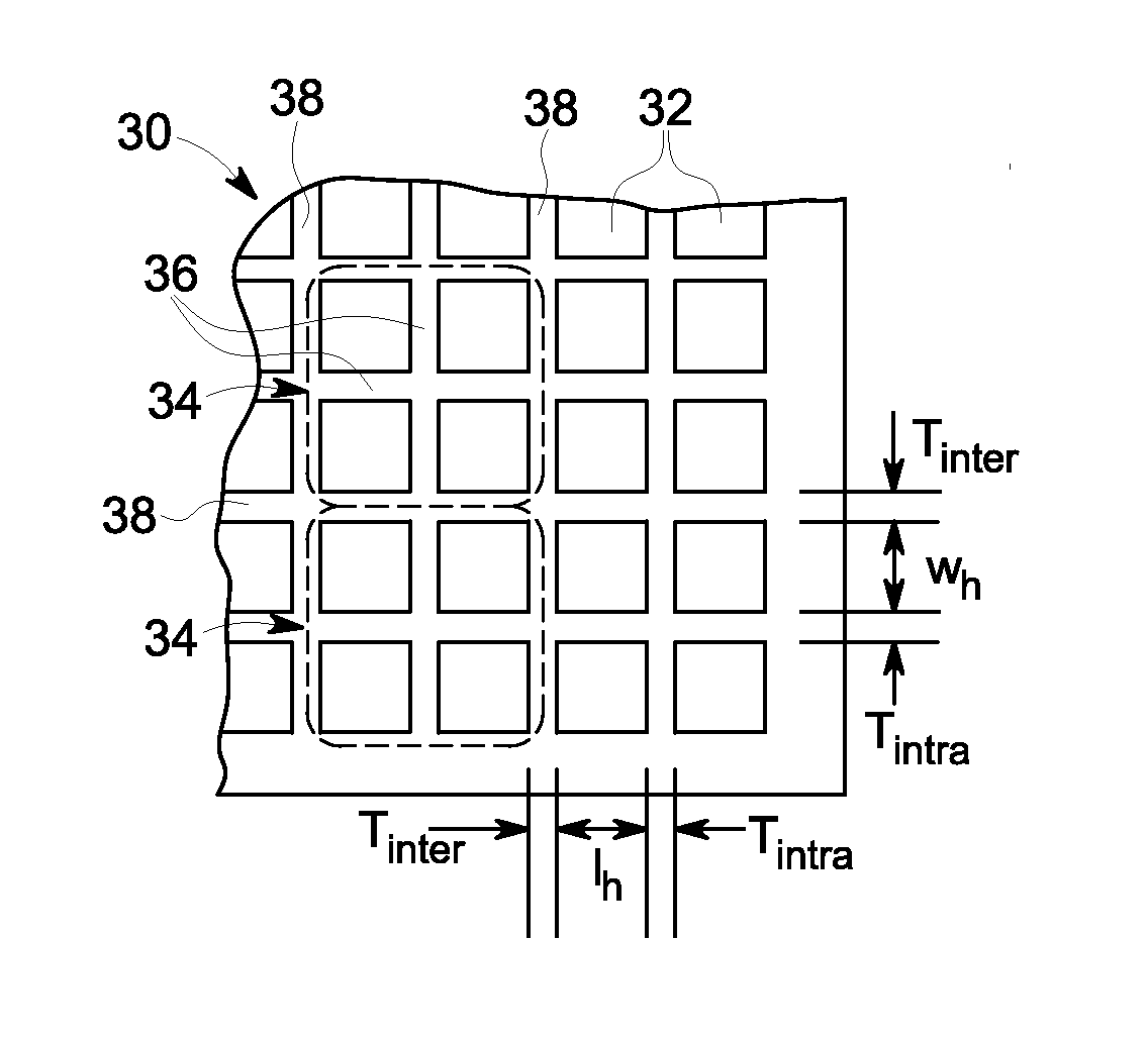
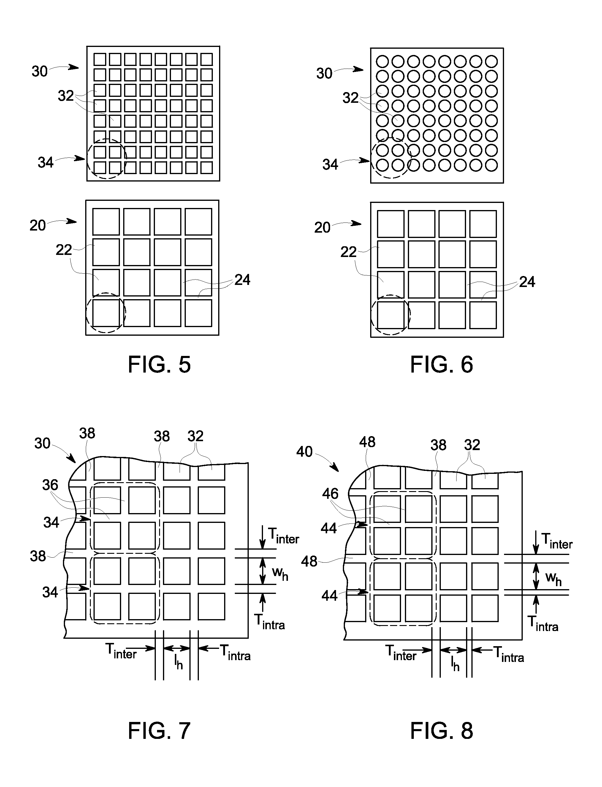
[0071]Referring now to the drawings, FIG. 5 shows the present invention, in which a collimator 30 may be associated with a pixelated detector 20. While prior art collimators for use with pixelated detectors have one collimator hole or channel per detector pixel, embodiments of the present invention utilize multiple holes per pixel. The collimator 30 has holes 32 arranged in groups 34, wherein each group 34 corresponds in overall size and location to a respective detector pixel 22 on the detector 20. This creates unique one-to-one registrations between each one of the groups 34 of holes 32 and its respective associated pixel element 22. In other words, each group of holes aligns with only one pixel element, and each pixel element is aligned with only one group of holes. The collimator 30 may be placed over the detector 20 so that each detector pixel 22 is covered by a group 34 of collimator holes 32, with the centroid of each group 34 of holes 32 being generally projectively aligned ...

third embodiment

[0076]the present invention is shown in FIGS. 10-12. In this embodiment, the intra-group septa 56 are recessed from the top and / or bottom surface of the collimator such that the height hs of these septa 56 is less than the overall height Hc of the collimator 50. It should be noted that although FIG. 10 only shows these septa 56 as being recessed from the “top” surface, it is equally within the scope of the present embodiment that the intra-group septa 56 can be recessed from the other (“bottom”) surface of the collimator, or from both surfaces. In a configuration according to this embodiment, the overall height Hc of the collimator can be the same as that of an otherwise conventional collimator, or it can be made smaller. Also, although FIGS. 10-12 show the thickness Tintra of the intra-group septa 56 as being smaller than the thickness Tinter of the inter-group septa 58, it is within the scope of this embodiment that these thicknesses (Tintra and Tinter) can optionally be the same....

second embodiment

[0081]Rows 9 and 10 show modifications made in which the collimator also uses four holes per pixel, but also includes reducing the intra-group septum thickness Tintra to 0.025 mm. This allows the inter-group septum thickness Tinter to be reduced, while still maintaining a thin collimator (i.e., very low Hc) with high sensitivity and low septal penetration. Rows 11 and 12 show the intra-group septum thickness Tintra being further reduced to 0.020 mm, which enables the inter-group septum thickness Tinter and collimator height Hc to remain about the same as rows 9 and 10, but with improved sensitivity compared to rows 9 and 10.

TABLE 1Inter-groupIntra-groupPixelCollimatorSeptumResolutionSeptumPitch,Height,Thickness,RelativeFWHMThickness,RowPpHcTinterSensitivitySensitivity,@ 3.0 cmSeptalTintra#(mm)Material(mm)(mm)(cpm / μCi)RS(mm)Penetration(mm)Comments11.6 W9.40.3819721.005.0611.44%N / AGM actual22.46Pb21.00.4012670.644.8000.87%N / AGE actual32.46Pb19.30.4015110.7664.9991.28%N / ALower GE heig...


PUM


Abstract

A collimator for collimating high-energy photons, which may be used in medical imaging (e.g., nuclear medicine). The collimator has holes through the thickness (height) of the collimator, with the holes arranged in groups or clusters. The collimator may be used with a detector having an array of pixels, wherein each group of holes may be associated with a corresponding pixel, thereby providing multiple collimator holes per pixel. In one embodiment, each group of holes has septa of a given width separating the holes in that group, and each group of holes is separated from neighboring groups by septa of another, greater width. In another embodiment, the intra-group septa may be recessed from the top and/or bottom surface(s) of the collimator such that these septa have a smaller thickness (height) than the inter-group septa.

Description

BACKGROUND OF THE INVENTION[0001]The present invention relates generally to collimators for collimating photons, and more particularly to collimators for collimating high-energy photons for use in medical imaging, such as in nuclear medicine.[0002]In most forms of medical diagnostic imaging, images are created by one of two methods: transmission or emission. Transmission imaging occurs when radiation is directed through a patient and onto a radiation detector, such as when using X-rays in X-ray imaging (XR) or Computed Tomography imaging (CT). Emission imaging occurs when radiation in the form of a radiopharmaceutical is injected into a patient (or ingested or inhaled by the patient) and radioactive particles are emitted by the patient's body, such as when gamma photons are emitted and detected in Single Photon Emission Computed Tomography (SPECT) or Positron Emission Tomography (PET). In both transmission and emission imaging, the detectors used are selected based on their sensitiv...

Claims


Application Information

Patent Timeline
IPC IPC(8): G01T1/17G21K1/02
CPCG21K1/025
Inventor WARTSKI, NURITBLEVIS, IRABISHARA, NESMA
Owner GE MEDICAL SYST ISRAEL
Why Eureka
Try Eureka