Method for disposing fine objects, apparatus for arranging fine objects, illuminating apparatus and display apparatus

a technology for arranging fine objects and illuminating apparatus, which is applied in the direction of liquid/fluent solid measurement, fluid pressure measurement, peptide, etc., can solve the problem of inability to control the direction of the object, and achieve the effect of reducing costs, labor and costs

Active Publication Date: 2013-07-04
SHARP KK
View PDF25 Cites 46 Cited by
  • Summary
  • Abstract
  • Description
  • Claims
  • Application Information

AI Technical Summary

Benefits of technology

[0075]According to this embodiment, the effects of the invention become especially remarkable. This is because, for cases in which a plurality of fine objects are disposed on the substrate, conventional common methods using a manipulator or the like would involve costs and time generally proportional to the number of fine objects whereas use of the present invention makes the costs and time hardly depend on the number of the fine objects.
[0076]Also, in one embodiment, there is provided an arranging apparatus using the method for disposing fine objects to dispose the fine objects onto the substrate, the arranging apparatus comprising:
[0077]a fluid introducing section for introducing a fluid containing the fine objects onto the substrate; and
[0078]an electromagnetic force applying section for applying electromagnetic force to the substrate.
[0079]According to this embodiment, the arranging apparatus is an apparatus for actually executing the method for disposing fine objects onto a substrate in this invention. Therefore, it becomes possible to dispose the fine objects in a predetermined orientation at predetermined positions on the substrate, as has been impossible by conventional techniques using dielectrophoresis. Also, in comparison with arranging apparatuses using the conventional common method in which fine objects are grasped with a manipulator or the like and disposed on a substrate, the arranging apparatus of this embodiment has no necessity for sophisticated alignment among the manipulator, the fine objects and the substrate, making it possible to achieve the arrangement of the fine objects at lower costs and with simplicity.
[0080]On condition that a plurality of fine objects are disposed on the substrate, in particular, superiority of this arranging apparatus to arranging apparatuses employing the conventional common technique using the manipulator or the like is remarkable. For instance, labor of arranging ten fine objects by the manipulator is about ten times as heavy as that of arranging one fine object. By contrast, labor and costs for the arrangement with the arranging apparatus of this embodiment hardly depend on the number of fine objects that are arranged.

Problems solved by technology

In above conventional technique, however, the positions of the fine objects can be controlled, whereas directions thereof cannot be controlled.

Method used


Image

  • Method for disposing fine objects, apparatus for arranging fine objects, illuminating apparatus and display apparatus
  • Method for disposing fine objects, apparatus for arranging fine objects, illuminating apparatus and display apparatus
  • Method for disposing fine objects, apparatus for arranging fine objects, illuminating apparatus and display apparatus

Examples


first embodiment

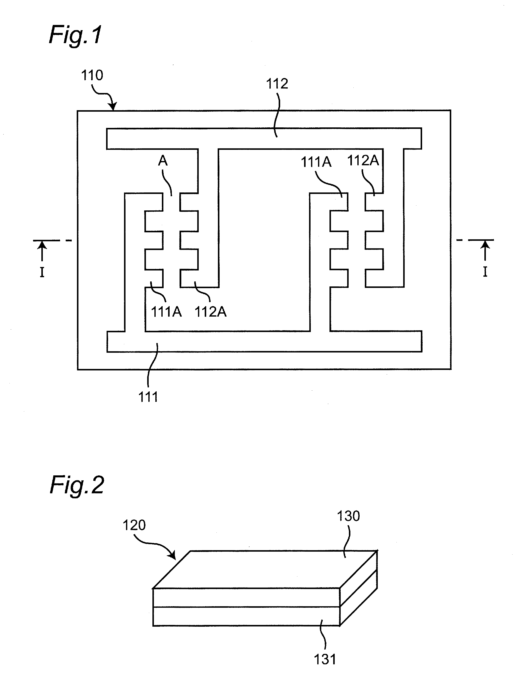
[0188]A first embodiment of the invention will be described with reference to FIGS. 1 to 9. In this embodiment, the fine objects solely have the alignment structure and the orientation in which the fine objects are disposed on a substrate is thereby controlled effectively.

[0189](Substrate Preparing Step)

[0190]In the substrate preparing step, a substrate 110 in which a first electrode 111 and a second electrode 112 are formed on a surface thereof as shown in FIG. 1 is prepared. In this case, the substrate 110 is an insulated substrate and the first, second electrodes 111, 112 are metal electrodes. The metal electrodes (first, second electrodes 111, 112) in desired electrode shapes can be formed on the surface of the substrate 110 by using a printing technique as an example. The first, second electrodes 111, 112 can be formed by uniform deposition of a metal film and a photoconductor film on the surface of the substrate 110, exposure and development of the photoconductor film into a d...

second embodiment

[0232]A second embodiment of the invention will be described below with reference to FIGS. 10 to 17. In this embodiment, not only fine objects but also the substrate has an alignment structure, and the fine objects are effectively controlled for their alignment in their arrangement onto the substrate depending on combinations of the alignment structure of the fine objects and the alignment structure of the substrate.

[0233](Substrate Preparing Step)

[0234]In this step, a substrate 210 with a first electrode 211 and a second electrode 212 formed on its surface as shown in FIG. 10 is prepared. In this case, the substrate 210 is an insulated substrate and the first, second electrodes 211, 212 are metal electrodes. Material and fabrication method for the substrate and the electrodes may be the same as in the first embodiment.

[0235]Surfaces of the first, second electrodes 211, 212 may be covered with an insulating film, which is not shown. In this case, the following effects are produced. ...

third embodiment

[0279]Next, a third embodiment of the invention will be described with reference to FIGS. 18 to 24. This embodiment is so constituted that alignment of fine objects 320 in their disposition onto a substrate 310 is effectively controlled by combinations of an alignment structure of the fine objects 320 and an external magnetic field generally parallel to the surface of the substrate 310.

[0280](Substrate Preparing Step)

[0281]In this step, a substrate 310 having a first electrode 311 and a second electrode 312 formed on its surface as shown in FIG. 18 is prepared. In this case, the substrate 310 is an insulated substrate and the first, second electrodes 311, 312 are metal electrodes. Material and fabrication method for the substrate 310 and the electrodes 311, 312 may be the same as in the first embodiment.

[0282]Surfaces of the first, second electrodes 311, 312 may be covered with an insulating film, which is not shown. In this case, the following effects are produced. In the later fin...


PUM

PropertyMeasurementUnit
lengthaaaaaaaaaa
diameteraaaaaaaaaa
distanceaaaaaaaaaa

Abstract

This method for disposing fine objects, in a substrate preparing step, prepares a substrate having specified positions where fine objects (120) are to be disposed in an area where a first electrode (111) and a second electrode (112) face each other, and in a fluid introducing step, a fluid (121) is introduced on the substrate (110). The fluid (121) contains a plurality of the fine objects (120). The fine objects (120) are diode elements, each of which has, as an alignment structure, a front side layer (130) composed of a dielectric material, and a rear side layer (131) composed of a semiconductor. In the fine object disposing step, by applying an AC voltage to between the first electrode (111) and the second electrode (112), the fine objects (120) are disposed by dielectrophoresis with the front side layer (130) facing up at the predetermined positions in the area (A) where the first electrode (111) and the second electrode (112) face each other.

Description

TECHNICAL FIELD[0001]The present invention relates to a disposing method for arranging fine objects on a substrate, an arranging apparatus based on the disposing method, and an illuminating apparatus as well as a display apparatus formed with use of the disposing method.BACKGROUND ART[0002]A conventional method for disposing fine objects at predetermined positions on a substrate is disclosed in Patent Literature 1 (U.S. Pat. No. 6,536,106 specification).[0003]In the disclosure of Patent Literature 1, as shown in FIG. 58, an insulating medium (liquid) including nanowires 9925 is introduced onto a substrate 9970 patterned with a left side electrode 9950 and a right side electrode 9953, and a voltage is then applied between the left side electrode 9950 and the right side electrode 9953. Action of an electric field produced by the voltage on the nanowires 9925 causes so-called dielectrophoretic effect and the nanowires 9925 are thereby disposed so as to bridge finger-like portions 9955 ...

Claims


Application Information

Patent Timeline
Patent Type & Authority Applications(United States)
IPC IPC(8): C25D13/00H01L27/15H01L21/479
CPCH01L33/24H01L25/0753H01L2924/12041H01L33/18H01L33/32C25D13/00H01L21/479H01L27/156H01L2224/08238H01L24/75H01L24/80H01L24/97H01L2224/75723H01L2224/80143H01L2224/95101H01L2224/95145H01L2224/97H01L2224/7598H01L2224/75655H01L24/95H01L2924/00H01L2924/15788H01L2924/12042H01L2924/12036H01L2924/14
Inventor SHIBATA, AKIHIDENEGISHI, TETSUKOMIYA, KENJIYAOI, YOSHIFUMISHIOMI, TAKESHIIWATA, HIROSHITAKAHASHI, AKIRA
Owner SHARP KK
Why Eureka
Try Eureka