
Vehicle seat devices

Active Publication Date: 2013-07-04
TS TECH CO LTD +1
View PDF12 Cites 20 Cited by
  • Summary
  • Abstract
  • Description
  • Claims
  • Application Information

AI Technical Summary

Benefits of technology

The invention is about a vehicle seat device that has side supports with a upholstery cover layer that is fixed to a frame in the side support while stretched out. The invention solves the issue of the cover layer becoming wrinkled and poor in appearance by allowing the ends of the cover layer to move in relation to the frame. This results in the cover layer becoming pulled onto the surface of the frame via protrusions, preventing wrinkling. Additionally, the invention also reduces the impact on the driver in the event of a rearward load.

Problems solved by technology

Therefore, the widths of the protruding portions could not be increased adequately, i.e., the distance between the protruding portions thereof could not be reduced sufficiently.
If the tension of the upholstery cover layers of the side supports is decreased in an effort to reduce the resistance imposed by the upholstery cover layers, if the width of the protruding portions is reduced, the surfaces of the side supports are likely to become wrinkled, thereby making the side supports aesthetically poor in appearance.

Method used


Image

  • Vehicle seat devices
  • Vehicle seat devices
  • Vehicle seat devices

Examples


first embodiment

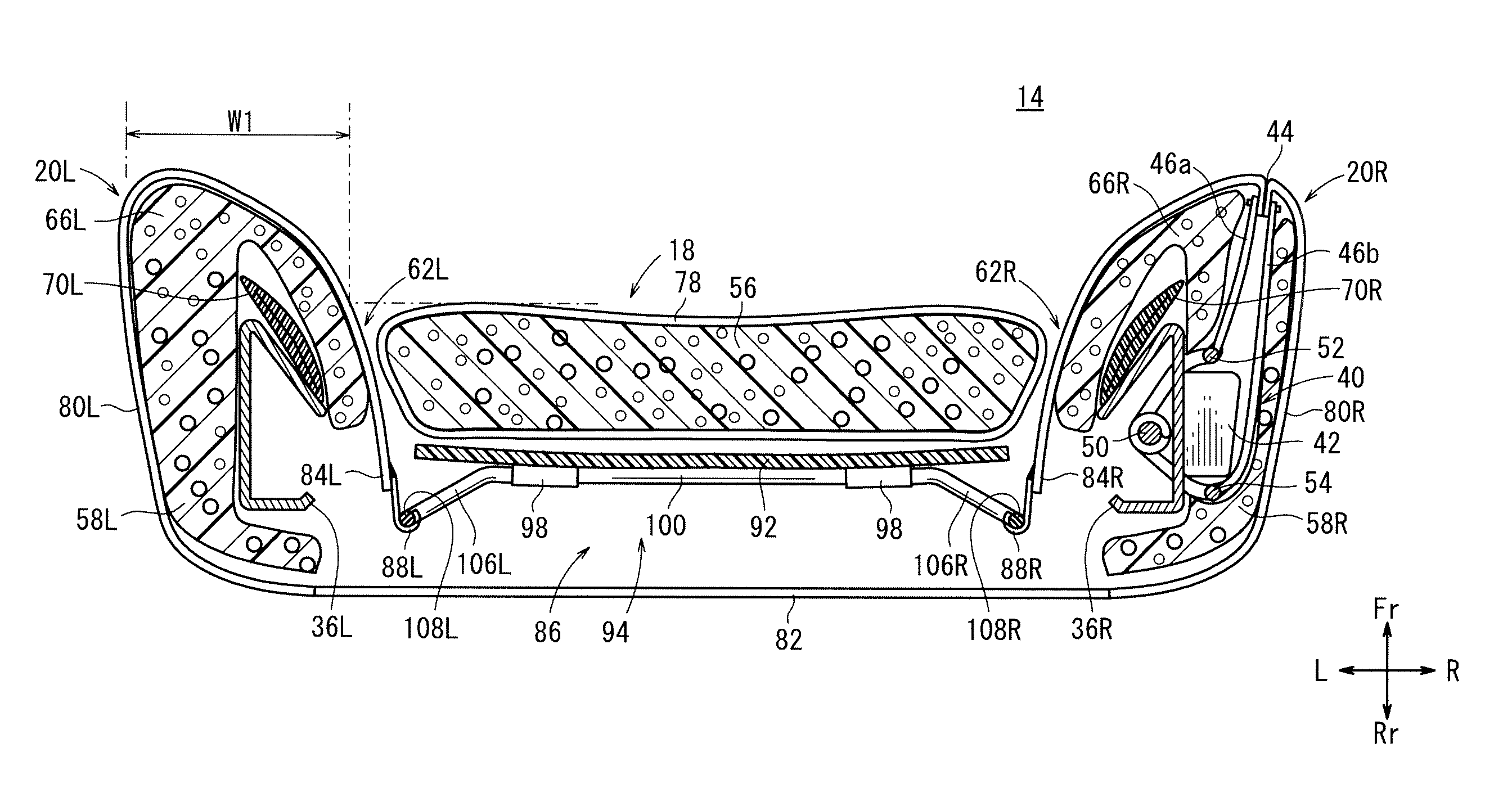
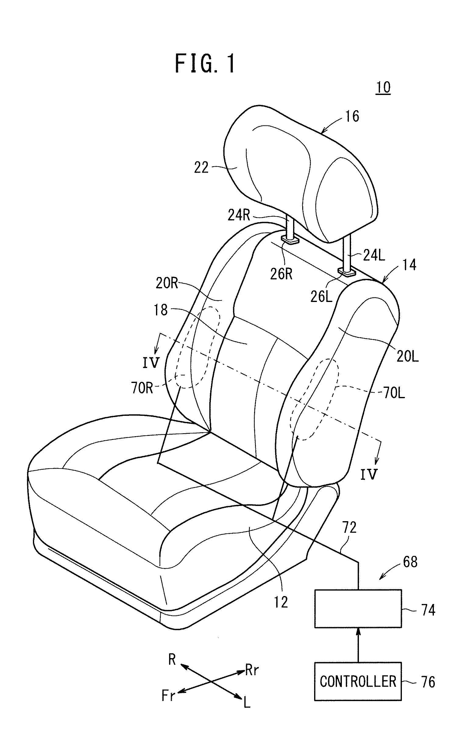
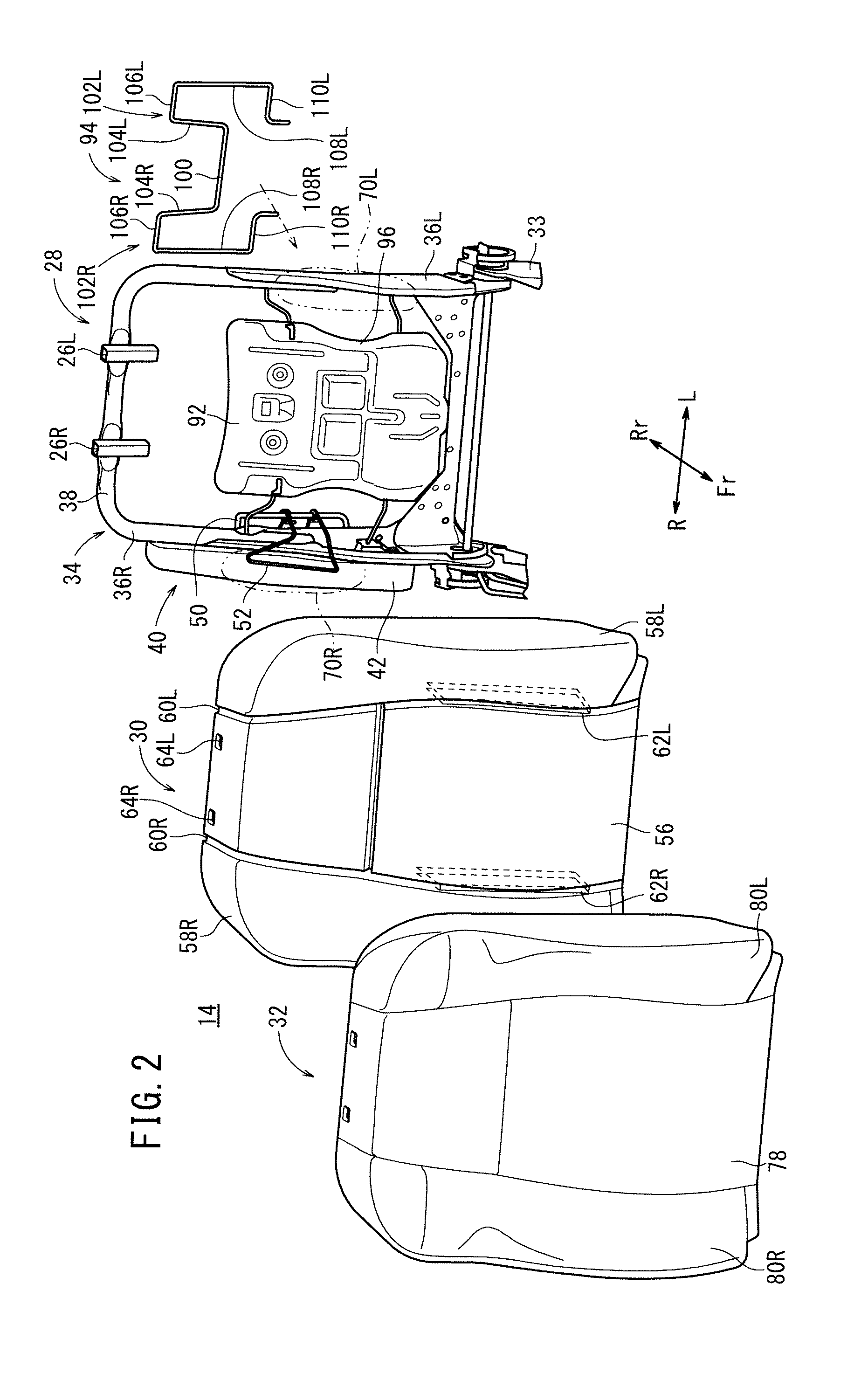
[0033]A vehicular seat device (first seat device) 10 according to a first embodiment of the present invention will be described below with reference to FIGS. 1 through 7. In the following description, when it is necessary to distinguish between left and right components, the components are denoted by reference characters together with a suffix “L” or “R”. When the components do not need to be distinguished from each other, the components are denoted by reference characters alone without the appended suffixes.

[0034]The first seat device 10 may be used as a driver's seat for automobiles (vehicles), for example. As shown in FIG. 1, the first seat device 10 includes a seat cushion 12 mounted on a non-illustrated vehicle body for supporting the buttocks and thighs of the driver, a seat back 14 tiltably supported on the rear end of the seat cushion 12 for supporting the back of the driver, and a headrest 16 vertically and adjustably mounted on the upper end of the seat back 14 for support...

second embodiment

[0074]A vehicular seat device (second seat device) 300 according to a second embodiment of the present invention will be described below with reference to FIG. 9. Constituent parts of the second embodiment, which are identical to those of the first embodiment, are denoted by identical reference characters, and duplicate descriptions of such parts will be omitted.

[0075]As shown in FIG. 9, the second seat device 300 does not have the support wires 90a, 90b, but has a pressure bearing member 301, which differs in shape from the pressure bearing member 10 of the first seat device 10. More specifically, the pressure bearing member 301 comprises a plurality of (three in FIG. 9) laterally extending S-shaped springs 302. Ends of each of the S-shaped springs 302 are fixed to the side frame members 36. The first wires 104 and the fourth wires 110 of the flexible member 94 are held by clips on two of the S-shaped springs 302. The second embodiment offers the same advantages as those of the fir...


PUM


Abstract

Vehicle seat devices are provided with: a backrest; side supports that are disposed on both sides of the backrest, and that have protruding sections that protrude further forward than the backrest; a mechanism for adjusting the degree of restraint that changes the width of the protruding sections; a frame disposed inside the side supports; and a movable member that is disposed on the frame, and that displaceably holds the ends of a side surface leather material of the side supports in relation to the frame.

Description

TECHNICAL FIELD[0001]The present invention relates to a vehicular seat device (vehicular seat devices) having side supports on both sides of a backrest.BACKGROUND ART[0002]Heretofore, vehicular seat devices have widely been known, which include side supports on both sides of a backrest for restraining a passenger in a vehicle, in order to prevent the passenger from becoming tilted in attitude under centrifugal forces while the vehicle is traveling.[0003]As one type of such a vehicular seat device, a vehicular seat device is disclosed in which portions (protruding portions) of side supports, which project forwardly from a backrest, have widths that are changed in order to enable the extent to which the passenger is restrained to be variable (Japanese Laid-Open Patent Publication No. 06-284942).SUMMARY OF INVENTION[0004]Usually, each of the side supports has an upholstery cover layer, an end portion of which is introduced into the side support (or the backrest) between the backrest an...

Claims


Application Information

Patent Timeline
IPC IPC(8): B60N2/427B60N2/22B60N2/90
CPCB60N2/4415B60N2/449B60N2/66B60N2/42745B60N2/427B60N2/5858B60N2/22B60N2/914B60N2/986B60N2/99B60N2/665B60N2/2222
Inventor SUGIYAMA, SHINJIKIKUCHI, MASATOMOCHIZUKI, HARUKIYOSHIUCHI, SHUTOKIKUCHI, NOBUKAZU
Owner TS TECH CO LTD
Learn More