Electronic ballast for lighting unit and lighting apparatus

Inactive Publication Date: 2013-07-04
OSRAM GMBH
View PDF3 Cites 22 Cited by
  • Summary
  • Abstract
  • Description
  • Claims
  • Application Information

AI Technical Summary

Benefits of technology

[0026]According to an embodiment of the present disclosure, the startup of the inverter can be made later than that of the PFC circuit by use of the controller, so that the output voltage can reach the rated value meeting the requirements for starting the discharge lamp, thereby prolonging the service life of the discharge lamp.
[0027]Further, by forcing the inverter to be started up after the output voltage of the PFC circuit is stabilized, the electronic ballast according to the embodiment of the present disclosure can prevent the inverter from being started up when the output voltage of the

Problems solved by technology

There are three problems in the electronic ballast circuit of the prior art.
Thus, the startup time and startup current of the discharge lamp cannot meet requirements in ANSI82.11, which has an adverse effect on the discharge lamp's life.
3. For the PFC circuit of this type, there exists an issue of output voltage overshooting (the output voltage exceeds the

Method used


Image

  • Electronic ballast for lighting unit and lighting apparatus
  • Electronic ballast for lighting unit and lighting apparatus
  • Electronic ballast for lighting unit and lighting apparatus

Examples


Example

[0032]In the following, the preferred embodiments of the present disclosure will be described in detail with reference to the accompany drawings. It is noted that in this specification and the accompany drawings, the same or similar reference numerals are used to indicate constitutive elements having substantially the same or similar functions and constitutions, and repeated explanation for such constitutive elements is omitted.

[0033]Hereinafter, features of the present disclosure are described with specific embodiments.

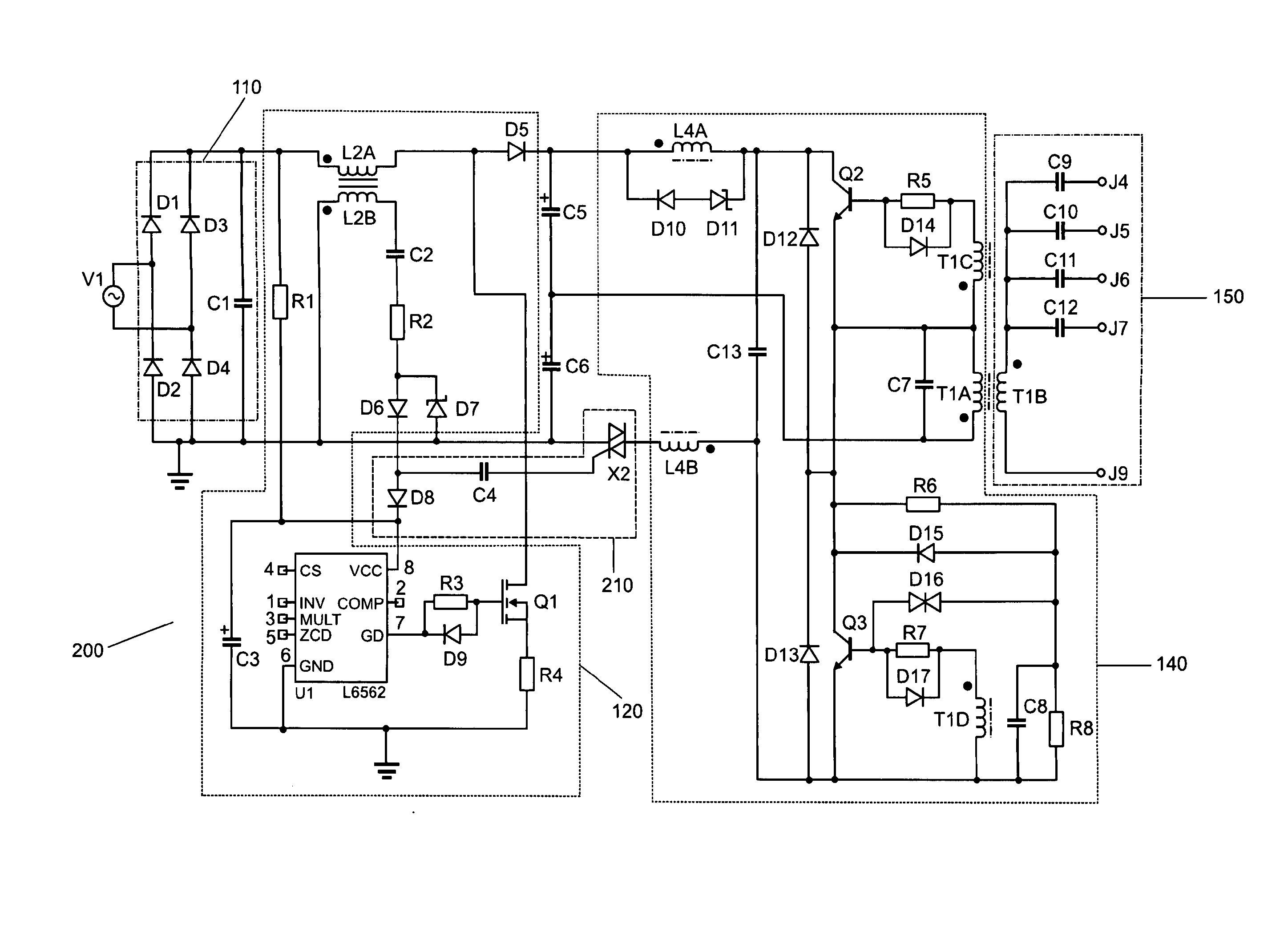
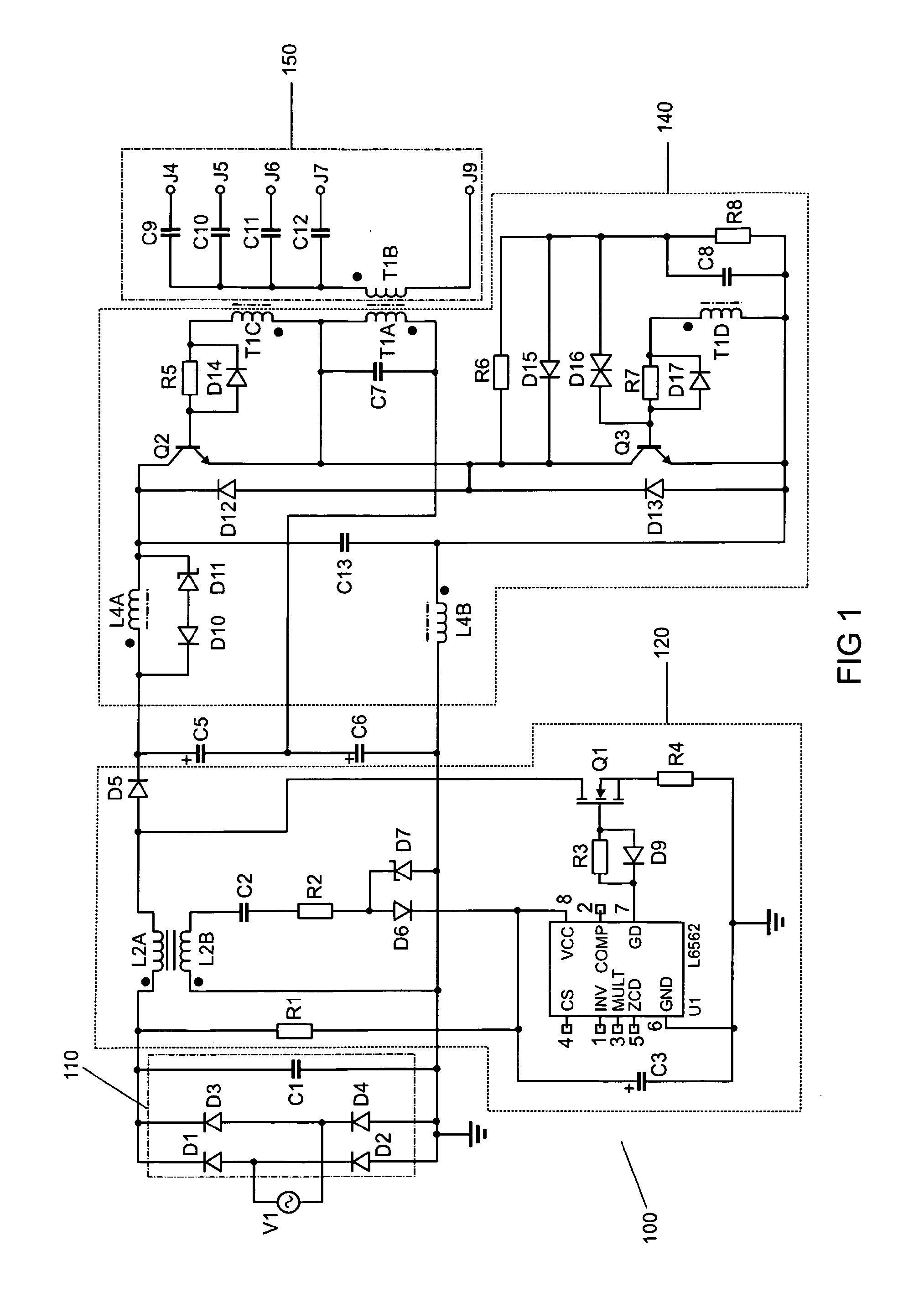
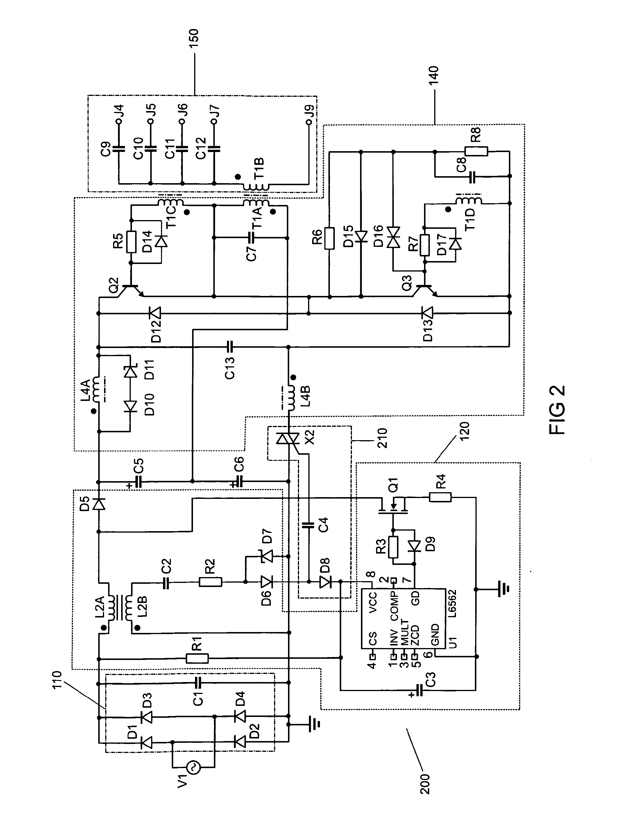
[0034]FIG. 2 is a schematic diagram illustrating an electronic ballast circuit 200 according to an embodiment of the present disclosure. Since other circuits than a control circuit 210 for startup of an inverter 140 in a half-bridge form are identical to that shown in FIG. 1, repeated explanation is omitted herein and only differences from FIG. 1 are described.

[0035]As shown in FIG. 2, a control circuit 210 for startup of the inverter 140 includes a switching device ...


PUM


Abstract

An electronic ballast for a lighting unit may include: a Power Factor Correction (PFC) circuit, an inverter, and a control circuit for controlling startup of the inverter, wherein the control circuit is coupled between the PFC circuit and the inverter and includes: a switching device coupled in a startup loop for the inverter; a unidirectional conductive device coupled between a PFC power supply circuit for providing an operation current to a PFC controller of the PFC circuit and an input of the PFC controller, for preventing a startup current flowing through the PFC circuit from triggering the switching device; and a triggering device coupled to the switching device and a connection point between the unidirectional conductive device and the PFC power supply circuit, for controlling switch-on and -off of the switching device.

Description

FIELD OF THE INVENTION[0001]The present invention relates to the field of lighting. More particularly, the present invention relates to an electronic ballast for a lighting unit, and a lighting apparatus including the electronic ballast.BACKGROUND OF THE INVENTION[0002]A lighting unit such as a gas discharge lamp requires a ballast, so as to adapt to a power supply of an electrical system. Due to higher light output, the electronic ballast which drives, in a high frequency manner, the discharge lamp to illuminate has taken the place of the traditional ballast and starters and been applied widely. In addition to passive components such as transformers, inductor coils and capacitors, the electronic ballast also includes active components such as transistors and an integrated circuit, so as to implement power-supply frequency conversion or current waveform conversion.[0003]Instant startup electronic ballast circuit for a fluorescent lamp mainly includes an Active Power Factor Correctio...

Claims


Application Information

Patent Timeline
IPC IPC(8): H05B41/36
CPCH05B41/2825Y02B20/185H05B41/36Y02B20/00
Inventor DAI, HONGGUO, YUANCHENGGAO, WEIMA, CHANGSONG
Owner OSRAM GMBH
Why Eureka
Try Eureka