Drill and method of manufacturing machined product using the same

a technology of drilling and machined products, which is applied in the direction of manufacturing tools, twist drills, wood boring tools, etc., can solve the problems of affecting the drilling performance the inner wall of the drilled hole is likely to be deformed, and the chip generated from each of the cutting edges is liable to be blocked at the joining location of the two flutes, etc., to achieve excellent drilling performance, reduce the situation, and large the effect of core thickness

Inactive Publication Date: 2013-07-04
KYOCERA CORP
View PDF8 Cites 26 Cited by
  • Summary
  • Abstract
  • Description
  • Claims
  • Application Information

AI Technical Summary

Benefits of technology

[0008]In the drills of the individual embodiments of the present invention, the first joining flute is obtained by joining the flutes and the clearance. It is therefore capable of reducing a situation that the chips discharged through the individual flutes are clogged at the joining location, while ensuring a large core thickness (inscribed circle) of the drill. This allows for both excellent drilling performance and excellent fracture resistance.

Problems solved by technology

However, in the drill having the two flutes thus joined together, the chips generated from each of the cutting edges are liable to be clogged at a joining location of the two flutes.
Consequently, due to heat generated at the joining location caused by the clogged chips, a workpiece is likely to be altered, and the inner wall of a drilled hole is likely to be deformed (surface roughness is likely to deteriorate).
Further, the chips clogged at the joining location of the flutes may increase the stress (cutting torque) exerted on the joining location during machining, thus causing a fracture of the drill.
Therefore, the flow of the chips passing through the individual flutes may be changed at the joining location, thus ruining the inner wall of the drilled hole.

Method used


Image

  • Drill and method of manufacturing machined product using the same
  • Drill and method of manufacturing machined product using the same
  • Drill and method of manufacturing machined product using the same

Examples


first embodiment

[0014]A first embodiment of the drill of the present invention is described below in details with reference to FIGS. 1 to 3.

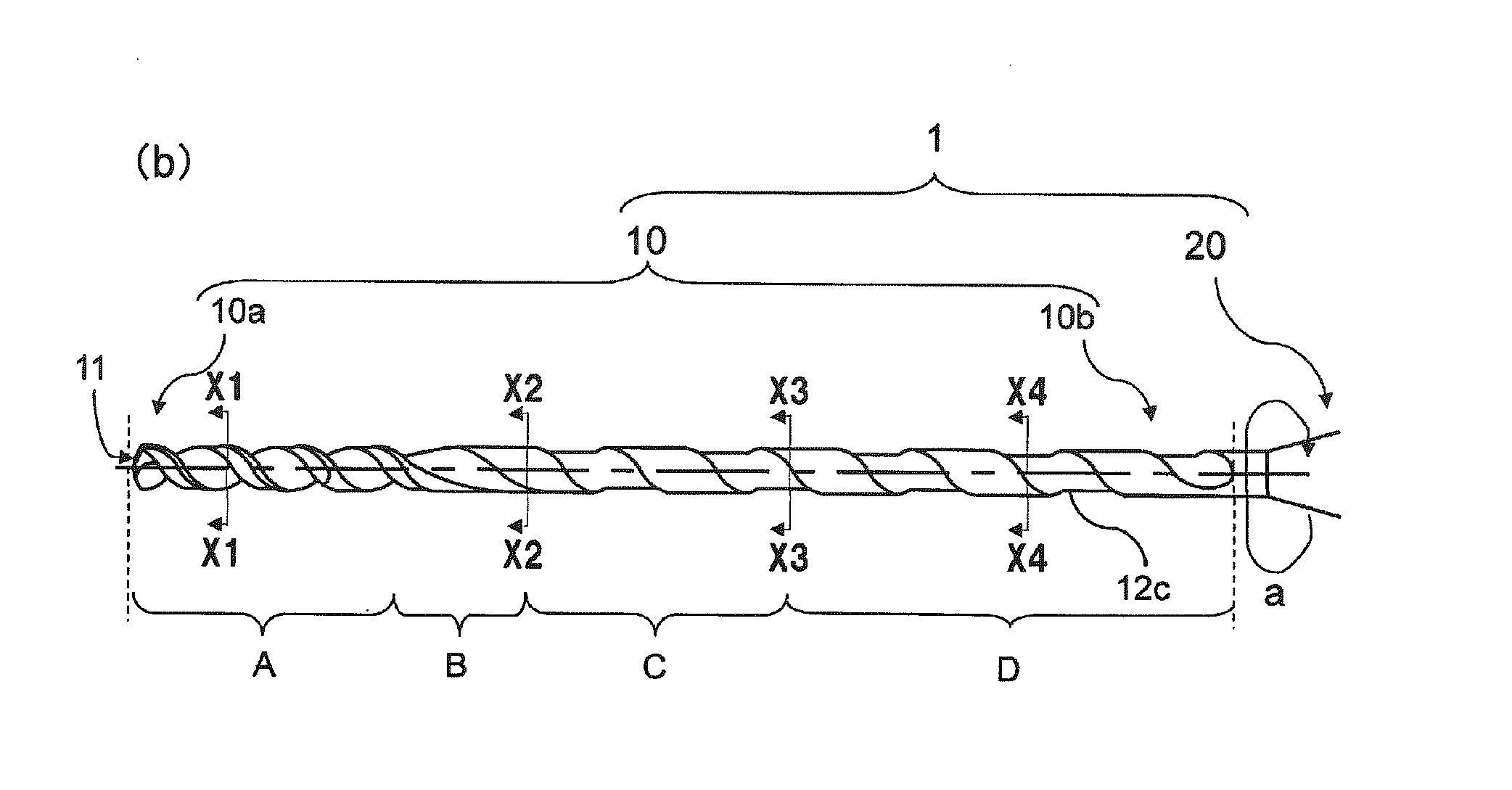
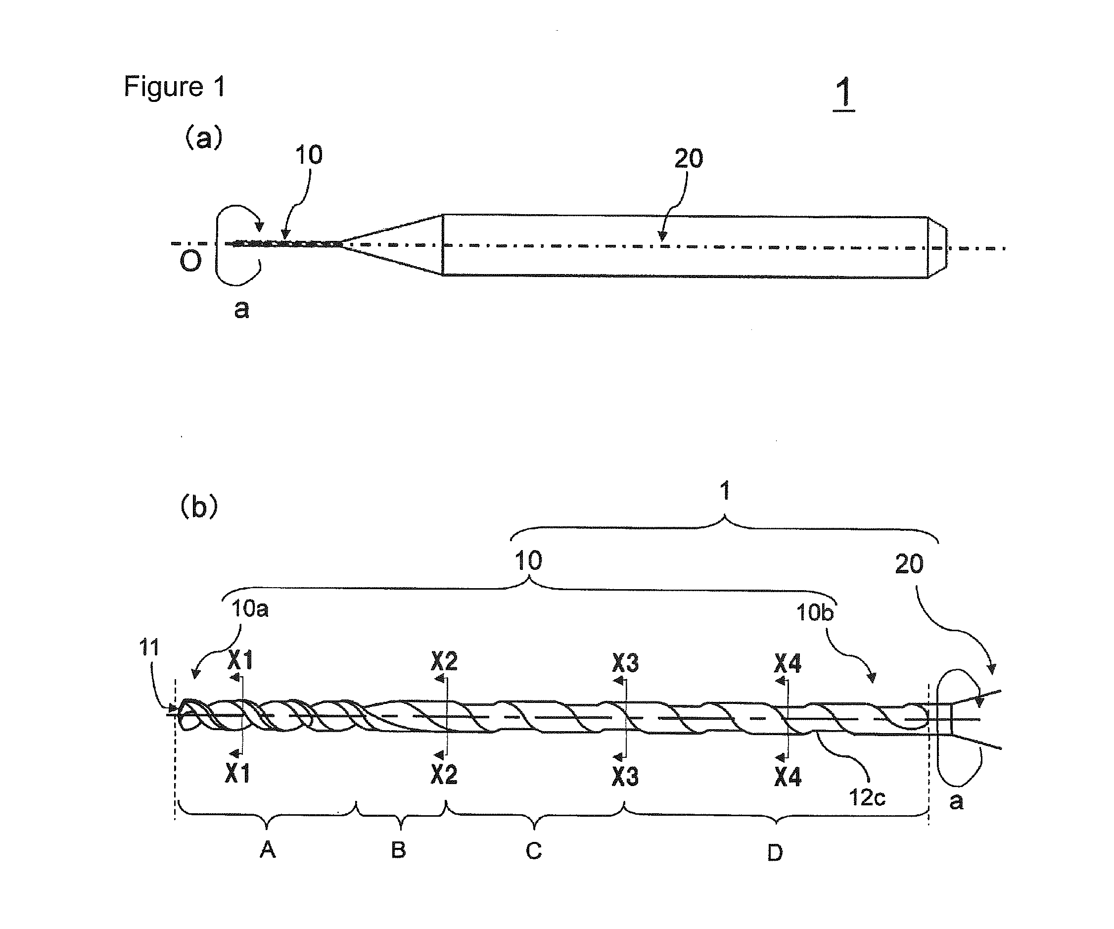
[0015]As shown in FIG. 1, the drill 1 of the present embodiment includes a body part 20 configured to be held by a rotary shaft of a machine tool, and a cutting part 10 disposed on one end side of the body part 20. The body part 20 is designed according to the shape of the rotary shaft of the machine tool. The cutting part 10 is contacted against a workpiece 30.

[0016]The cutting part 10 has a major role in a cutting process for the workpiece 30, and has a cylinder-like shape in the present embodiment. That is, the cutting part 10 has a relationship of T1=T2, where T1 is a diameter in a front end portion 10a, and T2 is a diameter in portions other than the front end portion 10a. The cutting part 10 has also a constant diameter from the front end portion 10a to a rear end portion 10b in a cross section perpendicular to a rotation axis O.

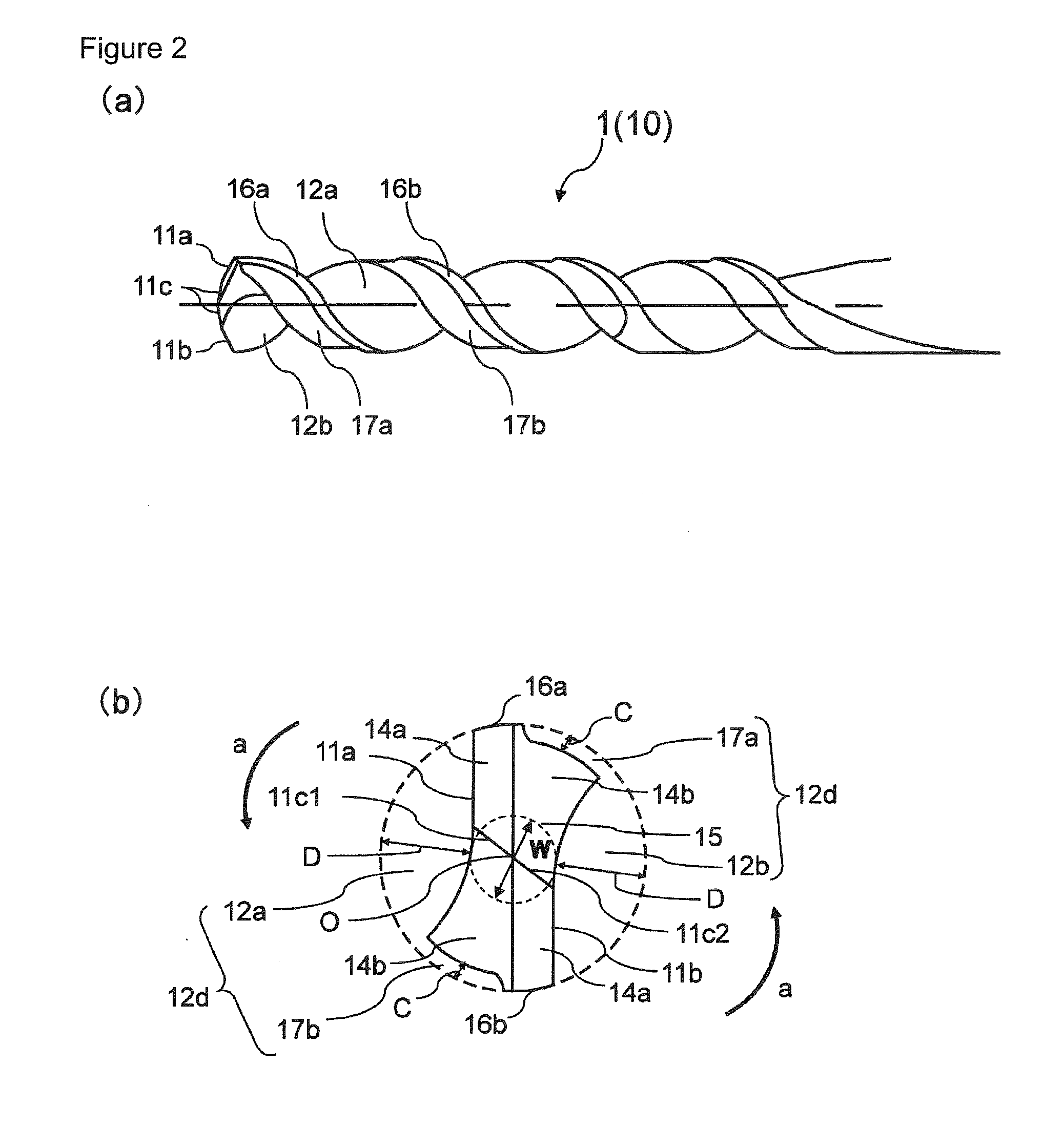
[0017]As shown in FIG. 2, ...

second embodiment

[0033]A drill according to a second embodiment of the present invention is described below. The basic configuration thereof is similar to that of the drill of the first embodiment, and therefore, the description is made by properly referring to FIGS. 1 to 3.

[0034]The drill 1 according to the present embodiment includes a cutting part with a cylinder-like shape 10 and a body part 20. The cutting part 10 has at a front end portion 10a thereof two cutting edges 11a and 11b located separately from each other, and two flutes 12a and 12b which are continuous with each of the two cutting edges 11a and 11b, and extend spirally toward a rear end portion 10b of the cutting part 10 until both join together. Both of the two flutes 12 and 12b reach a bottom portion 12a3 while having a larger depth from the periphery of the cutting part 10 as they separate from one end portion 12a1 in a sectional view. Both of the two flutes 12a and 12b have a smaller depth as going from the bottom portion 12a3 t...


PUM

PropertyMeasurementUnit
outer diameteraaaaaaaaaa
shapeaaaaaaaaaa

Abstract

A drill according to an embodiment of the present invention includes a body part and a cutting part with a cylinder-like shape. The cutting part includes two cutting edges located separately from each other at a front end portion of the cutting part, two flutes which are continuous with each of the two cutting edges and extend spirally toward a rear end portion of the cutting part, and a clearance which extends spirally from a side of the front end portion to a side of the rear end portion, and is recessed inward in reference to a periphery of the cutting part in a sectional view. The cutting part includes a first joining flute including at least one of the two flutes and the clearance being joined together. The first joining flute includes a bottom surface being outwardly protruding curve-like line in a sectional view. A method of manufacturing a machined product using the drill is also provided.

Description

TECHNICAL FIELD[0001]The present invention relates to a drill and a method of manufacturing a machined product using the drill.BACKGROUND ART[0002]Heretofore, for example, Japanese Unexamined Patent Publication No. 2007-307642 discloses a drill having, on the front end of a body thereof, two cutting edges and two spiral flutes connected to each of the two cutting edges, in which the two spiral flutes are joined together into a single flute at a position retreated by a predetermined amount from the front end of the body.[0003]However, in the drill having the two flutes thus joined together, the chips generated from each of the cutting edges are liable to be clogged at a joining location of the two flutes. Consequently, due to heat generated at the joining location caused by the clogged chips, a workpiece is likely to be altered, and the inner wall of a drilled hole is likely to be deformed (surface roughness is likely to deteriorate). Further, the chips clogged at the joining locatio...

Claims


Application Information

Patent Timeline
Patent Type & Authority Applications(United States)
IPC IPC(8): B23B51/02
CPCB23B51/02B23B2251/406Y10T408/03B23B2251/44Y10T408/9097B23B2251/426B23B51/011
Inventor OGAWA, HIROSHI
Owner KYOCERA CORP
Why Eureka
Try Eureka