On-Vehicle Apparatus, And Method And Computer Program For Transmitting Positional Information

a position information and vehicle technology, applied in the direction of memory systems, memory adressing/allocation/relocation, instruments, etc., can solve the problem of severely limited storage capacity of the memory, and achieve the effect of reducing the accuracy of vehicle travel routes computed from the recorded position information pieces

Active Publication Date: 2013-07-04
JVC KENWOOD CORP A CORP OF JAPAN
View PDF5 Cites 11 Cited by
  • Summary
  • Abstract
  • Description
  • Claims
  • Application Information

AI Technical Summary

Benefits of technology

[0029]This invention offers the advantage that a positional information piece can be repetitively recorded for a longer term while a reduction in accuracy of a vehicle travel route computed from the recorded positional information pieces can be suppressed.

Problems solved by technology

Generally, an on-vehicle apparatus can provide only a narrow space for such a memory, and the storage capacity of the memory is severely limited.

Method used


Image

  • On-Vehicle Apparatus, And Method And Computer Program For Transmitting Positional Information
  • On-Vehicle Apparatus, And Method And Computer Program For Transmitting Positional Information
  • On-Vehicle Apparatus, And Method And Computer Program For Transmitting Positional Information

Examples


first embodiment

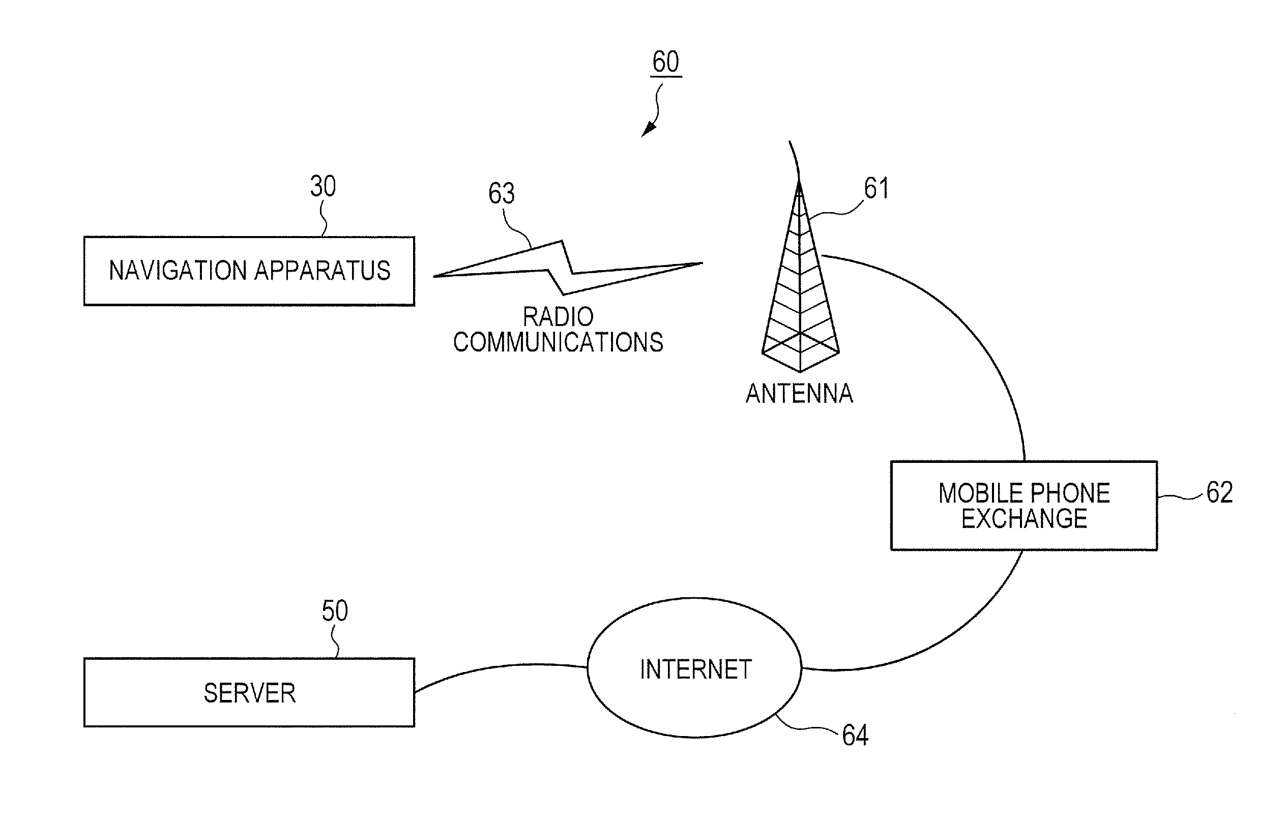
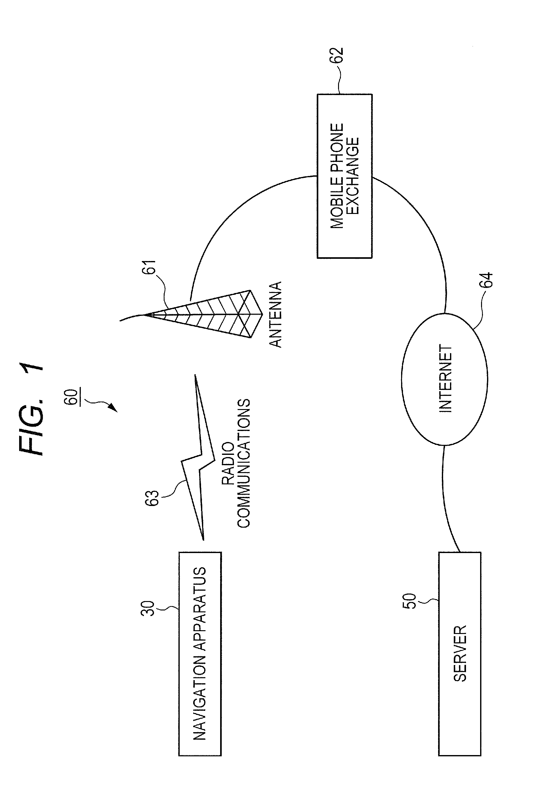
[0083]FIG. 1 shows a positional information collecting system 60 according to a first embodiment of this invention.

[0084]As shown in FIG. 1, the positional information collecting system 60 includes a navigation apparatus 30, a server 50, a radio antenna 61, and a mobile phone exchange 62. The radio antenna 61 is provided in a mobile phone base station connected with the mobile phone exchange 62. In general, a plurality of mobile phone base stations are connected with the mobile phone exchange 62. The mobile phone exchange 62 and the server 50 are connected via the Internet 64.

[0085]The navigation apparatus 30 can send and receive arbitrary information to and from the server 50 via the radio antenna 61, the mobile phone base station, the mobile phone exchange 62, radio communications 63, and the Internet 64. Similarly, the server 50 can send and receive arbitrary information to and from the navigation apparatus 30. The radio communications 63 are done between the navigation apparatus...

second embodiment

[0141]A second embodiment of this invention is similar to the first embodiment thereof except for design changes mentioned hereafter. In the second embodiment of this invention, a method of thinning out log data pieces in the storage device 34 is designed to further suppress a reduction in the accuracy of the route taken by the vehicle which is computed from non-erased log data pieces.

[0142]With reference to FIG. 8A, on a straight route 101 taken by the vehicle, there are equally-spaced positions (locations) 111, 112, and 113 at each of which a log data piece is generated and stored into the log buffer in the storage device 34.

[0143]In the case where the direction of travel of the vehicle remains unchanged and the straight route 101 is formed as shown in FIG. 8A, even if the log data piece generated at the position 112 is erased, the position 112 can be correctly recovered through interpolation calculating the middle point on a straight line between the positions 111 and 113 and lab...

third embodiment

[0160]A third embodiment of this invention is similar to the first embodiment thereof except for design changes mentioned hereafter. In the third embodiment of this invention, a method of thinning out log data pieces in the storage device 34 is designed to further suppress a reduction in the accuracy of the route taken by the vehicle which is computed from non-erased log data pieces.

[0161]With reference to FIG. 11A, on a route 201 taken by the vehicle, there are spaced positions (locations) 211, 212, and 213 at each of which a log data piece is generated and stored into the log buffer in the storage device 34. Each generated log data piece represents corresponding one of the positions 211, 212, and 213. In the case where a detour or by-road is absent from the portion of the route 201 between the positions 211 and 213 as shown in FIG. 11A, if the log data piece generated at the position 212 is erased, the route portion taken by the vehicle between the positions 211 and 213 can be uni...


PUM


Abstract

At every first prescribed timing, a positional information piece is generated. Each generated positional information piece represents a position of a vehicle which occurs at the corresponding first prescribed timing. Each generated positional information piece is written into one of storage areas in a storage device. At every second prescribed timing, positional information pieces in the storage areas are sent to a positional information collecting apparatus, and new positional information pieces are allowed to be written into the storage areas in which the sent positional information pieces are stored. In the event that sending the positional information pieces in the storage areas to the positional information collecting apparatus is impossible, a new positional information piece or pieces are allowed to be written into one or more of the storage areas which store a positional information piece or pieces having not been sent yet.

Description

CROSS-REFERENCE TO RELATED APPLICATIONS[0001]This application claims priority from Japanese patent application numbers 2011-289759, 2011-289760, and 2011-289761, filed on Dec. 28, 2011, the disclosures of which are hereby incorporated by reference.BACKGROUND OF THE INVENTION[0002]1. Field of the Invention[0003]This invention generally relates to an on-vehicle apparatus, and a method and a computer program for transmitting positional information. This invention particularly relates to a technology for transmitting information representative of the position of a vehicle to a positional information collecting apparatus.[0004]2. Description of the Related Art[0005]Japanese patent application publication number 2011-154494 discloses a traffic information collecting system in which on-vehicle apparatuses transmit probe information pieces concerning the travel trajectories or loci of related vehicles respectively, and a processing apparatus in a traffic information center collects the tran...

Claims


Application Information

Patent Timeline
Patent Type & Authority Applications(United States)
IPC IPC(8): G06F12/02
CPCG06F12/02G01C21/26G08G1/0112G08G1/096827G08G1/0969
Inventor SUZUKI, TAKUMI
Owner JVC KENWOOD CORP A CORP OF JAPAN
Why Eureka
Try Eureka