
Laser system and laser wavelength conversion

a laser and wavelength conversion technology, applied in laser details, instruments, optical devices for lasers, etc., can solve the problems of nonlinear optical crystal decay due to moisture for a long-term operation, no means ready to remove moisture on the inner wall of the cell, no means to recover any defect on the sealing structure of the cell, etc., to achieve the effect of preventing the decay of nonlinear optical crystal due to moistur

Inactive Publication Date: 2005-01-13
ORC MFG
View PDF13 Cites 13 Cited by
  • Summary
  • Abstract
  • Description
  • Claims
  • Application Information

AI Technical Summary

Benefits of technology

[0009] As arranged above, the laser system can generate laser beam stably for a long term. The nonlinear optical crystal is held in the hermetically sealed vessel (nonlinear optical crystal cell). The inner wall of the hermetically sealed vessel is covered with water-repellent coating. Dry inert gas (Ar, N2, etc.) is filled in the sealed vessel. In this way, the decay of the nonlinear optical crystal due to moisture can be prevented even for a long term operation.

Problems solved by technology

That is, there is a problem that the decay of the nonlinear optical crystals due to moisture for a long term operation cannot be prevented with the conventional method to avoid moisture.
In the case that dry gas is only sealed in the crystal cell, there is no means ready to remove the moisture on the inner wall of the cell.
Also there is no means to recover any defect occurred on the sealing structures of the cell.
Thus the transparency for the fourth harmonic laser wave is getting worse.
Therefore, the wavelength conversion efficiency falls down rapidly and the output power of the laser beam is reduced to a very small extent.

Method used


Image

  • Laser system and laser wavelength conversion
  • Laser system and laser wavelength conversion
  • Laser system and laser wavelength conversion

Examples


first embodiment

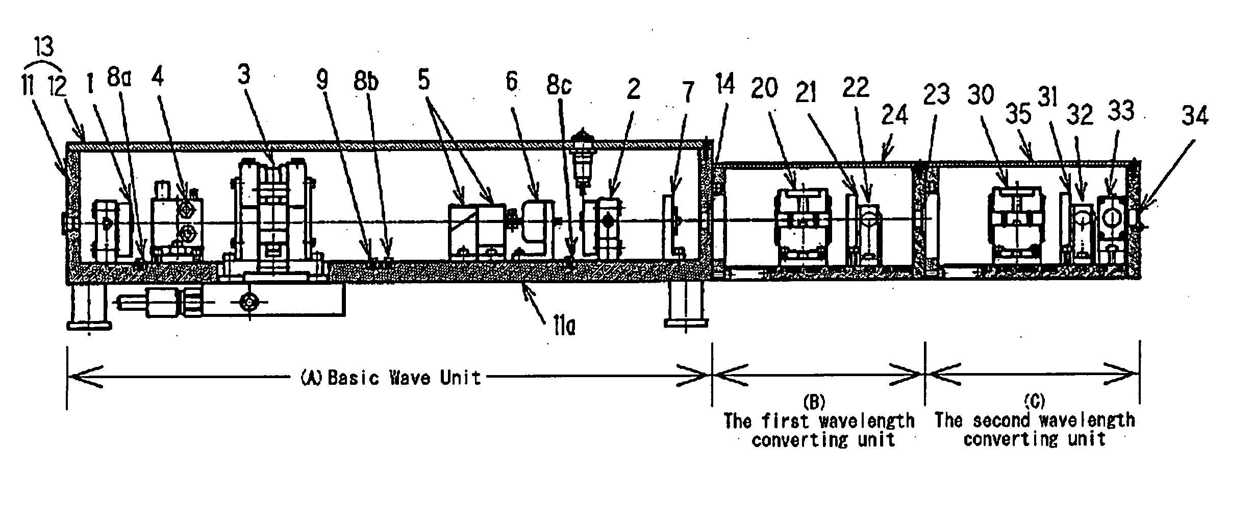
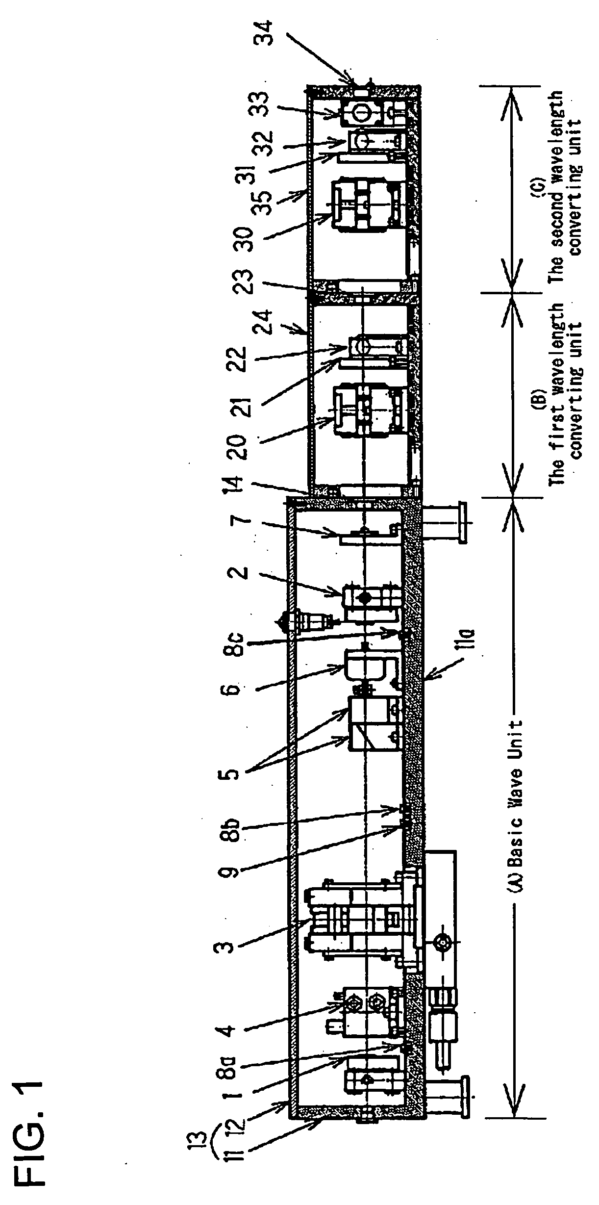
[0020]FIG. 1 shows the outline of the solid-state laser system according to this invention. A solid-state laser device, i.e. a laser diode, is employed as the laser light source. This solid-state laser system is the wavelength converting laser system. It is composed of a basic unit (A), the first wavelength converting unit (B) and the third wavelength converting unit (C).

[0021] The basic unit (A) includes the mirror (1) of the basic optical unit, a mirror (2), a pumping chamber unit (3), a Q-switch (4), a Brewster plate (5), a shutter (6), the first condenser lens (7) and so on. The mirror (1) and the mirror (2) constitute a laser resonator. The pumping chamber unit (3) is provided with solid-state laser material. The solid-state laser material is either one of Nd:YAG, Nd:YVO4, Nd:YLF and so on and is excited by a semiconductor laser diode.

[0022] The basic unit (A) is also provided with vessel (13). The vessel (13) is composed of a case (11) and a lid (12). The case (11) has a wind...

second embodiment

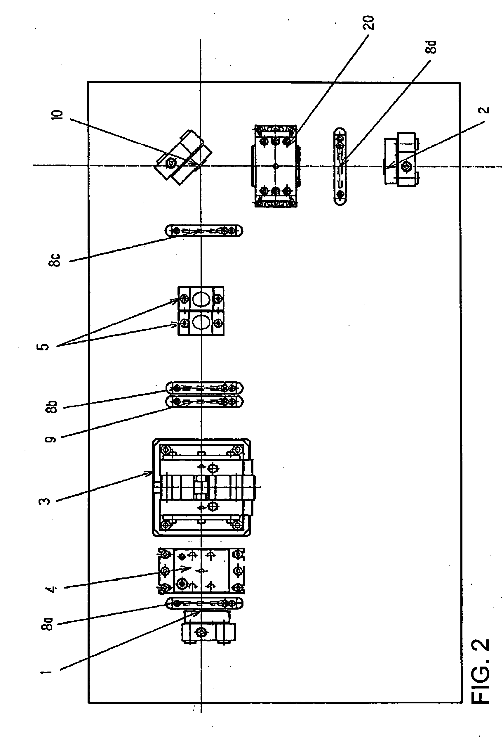
[0025]FIG. 2 shows the outline of the second harmonics laser system of the intra-chamber type according to the solid-state laser system of this invention. A solid-state laser device is used as the laser light source in this system. This system is the second harmonics laser system of intra-chamber type that includes the first nonlinear optical crystal unit (20) to convert the laser wave into the second harmonic of twice fundamental frequency and the heater (8d) in the laser resonator.

third embodiment

[0026]FIG. 3 shows the outline of the third and the fourth harmonics laser system of the intra-chamber type according to the solid-state laser system of this invention. A solid-state laser device is used as the laser light source. The first nonlinear optical crystal unit (20) and the second nonlinear optical crystal unit (30) to convert the laser wave into the third harmonic of three-time fundamental frequency or the fourth harmonic of four-time fundamental frequency are held in the laser resonator. As each optical component is the same as shown in FIG. 1, detail description is eliminated.

[0027]FIG. 4 shows the schematic cross section of the nonlinear optical crystal cell employed in the solid-state laser system according to the embodiment of this invention. This cell is employed in the first nonlinear optical crystal unit (20) or the second nonlinear optical crystal unit (30) as shown in FIGS. 1, 2 and 3. The first and the second nonlinear optical crystal units are generally called...


PUM

PropertyMeasurementUnit
wavelengthaaaaaaaaaa
humidityaaaaaaaaaa
humidityaaaaaaaaaa

Abstract

A laser system is enabled to generate laser beam stably for a long term by avoiding the decay of nonlinear optical crystals due to moisture. The fundamental laser wave at a wavelength of 1064 nm is emitted from the pumping chamber unit of the solid-state laser device. The fundamental laser wave enters the first nonlinear optical crystal unit (20). The wavelength of the laser beam is converted into a half by the first nonlinear optical crystal unit (20). The converted laser beam emanates out of the unit. The fundamental laser wave and the second harmonic laser wave are introduced into the second nonlinear optical crystal unit. Each of the laser beams is converted into the third harmonic laser wave (three-time fundamental frequency) or the fourth harmonic laser beam (four-time fundamental frequency) and the laser beam comes out of the exit-window (34). The nonlinear optical crystal units (20), (30) are held in a hermetically sealed cell whose inner surface is treated to be water-repellent. As the dry atmosphere is kept by means of isolating the nonlinear optical crystal from the outer air, the crystals can avoid decay due to moisture and the damage on the crystals can be reduced.

Description

BACKGROUND OF THE INVENTION [0001] 1. Field of the Invention [0002] This invention relates to a laser system and a laser wavelength conversion system, especially to such systems that the maintenance of those nonlinear optical crystals to convert wavelength is made easy. [0003] 2. Prior Art [0004] Generally, in a shortwave laser system, wavelength is converted by nonlinear optical crystal. General composition of an ultraviolet solid-state laser system, which is one of shortwave laser systems, is as follows. Wavelength of fundamental laser wave generated by Nd:YAG laser, Nd:YVO4 laser, Nd:YLF laser and so on is 1064 nm. The second harmonic is generated by nonlinear optical crystal. Moreover, the third or fourth harmonic is generated. LBO crystal or KTP crystal is employed to generate the second harmonic. LBO crystal, BBO crystal or GdYCOB crystal is employed to generate the third harmonic. BBO crystal, CLBO crystal or the like is employed to generate the fourth harmonic. [0005] Almost...

Claims


Application Information

Patent Timeline
Patent Type & Authority Applications(United States)
IPC IPC(8): G02F1/37G02F1/35H01S3/00H01S3/02H01S3/10H01S3/109H01S3/13
CPCG02F1/3501G02F2001/3505H01S3/005H01S3/0092H01S3/09415H01S3/11H01S3/1317H01S3/025G02F1/3505H01S3/1123
Inventor HASHIMOTO, SONHITONE, TOSHIFUMIAMANO, SATORU
Owner ORC MFG
Learn More