Vaporizer and various devices using the same and an associated vaporizing method

a technology of vaporizer and vaporizer, which is applied in the direction of separation processes, transportation and packaging, coatings, etc., can solve the problems of memory capacitance, deterioration of yield, and difficulty in realization after the 256 m bit limit, so as to reduce the content of carbon, accurately control the composition ratio of the film, and supply stably a raw material to the reaction part

Inactive Publication Date: 2008-08-14
M WATANABE CO LTD
View PDF27 Cites 9 Cited by
  • Summary
  • Abstract
  • Description
  • Claims
  • Application Information

AI Technical Summary

Benefits of technology

[0021]Since the vaporizer for MOCVD of this technology clogs a little, it enables a long term use and a stable supply of material to the reaction part, compared with the prior art.
[0026]Another object of the present invention is to provide a vaporizer that can be used for a long term without clogging or the like and that can supply stably a raw material to a reaction part.
[0027]Another object of the present invention is to provide a vaporizer, a deposition device, other various devices, and a vaporization method that can extremely reduce the content of carbon in the film, even in the as-deposited state, and accurately control the composition ratio of the film.

Problems solved by technology

The development of DRAM causes a problem concerning memory capacitance depending on microfabrication.
However, deterioration of yield by an increase of process number by a complicated process and increase of difference in steps is brought into question by such a three-dimensional structure, and it is assumed that realization after the 256 M bit limit is difficult.
However, in this technology, the metal filter can become clogged by the effect of several hours of vaporization.
As such, there is a problem that it cannot bear the long-term use.
However, the problem of clogging the small hole by the use for several hours, and not enduring a long-term use is also observed in this technology.
Moreover, the problem that a steady raw material supply cannot be achieved to a reaction is created because the solvent with the highest vapor pressure (in the following case, THF) evaporates promptly and an organometallic complex deposits and adheres on the heating face, when the raw material solution is a mixture solution of organometallic complexes, for instance, Sr(DPM)2 / THF, Bi(C6H5)3 / THF and Ta(OC2H5)5 / THF, and this mixture solution is evaporated by heating.
However, in the prior art, such a requisite is not necessarily complied with.

Method used


Image

  • Vaporizer and various devices using the same and an associated vaporizing method
  • Vaporizer and various devices using the same and an associated vaporizing method
  • Vaporizer and various devices using the same and an associated vaporizing method

Examples


embodiment 1

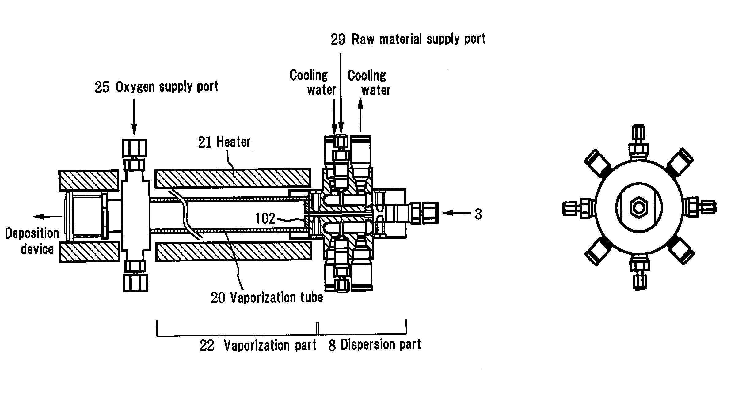
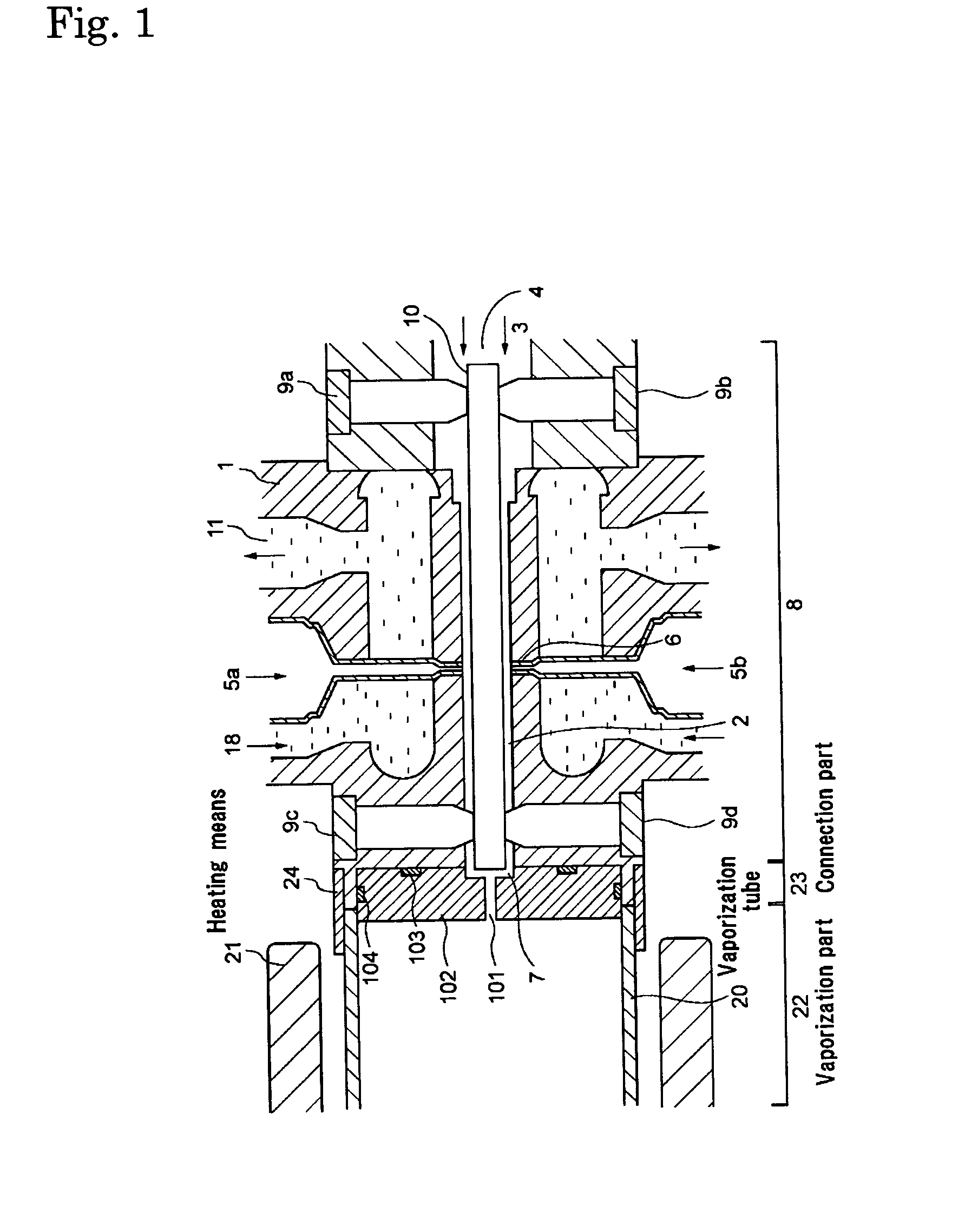
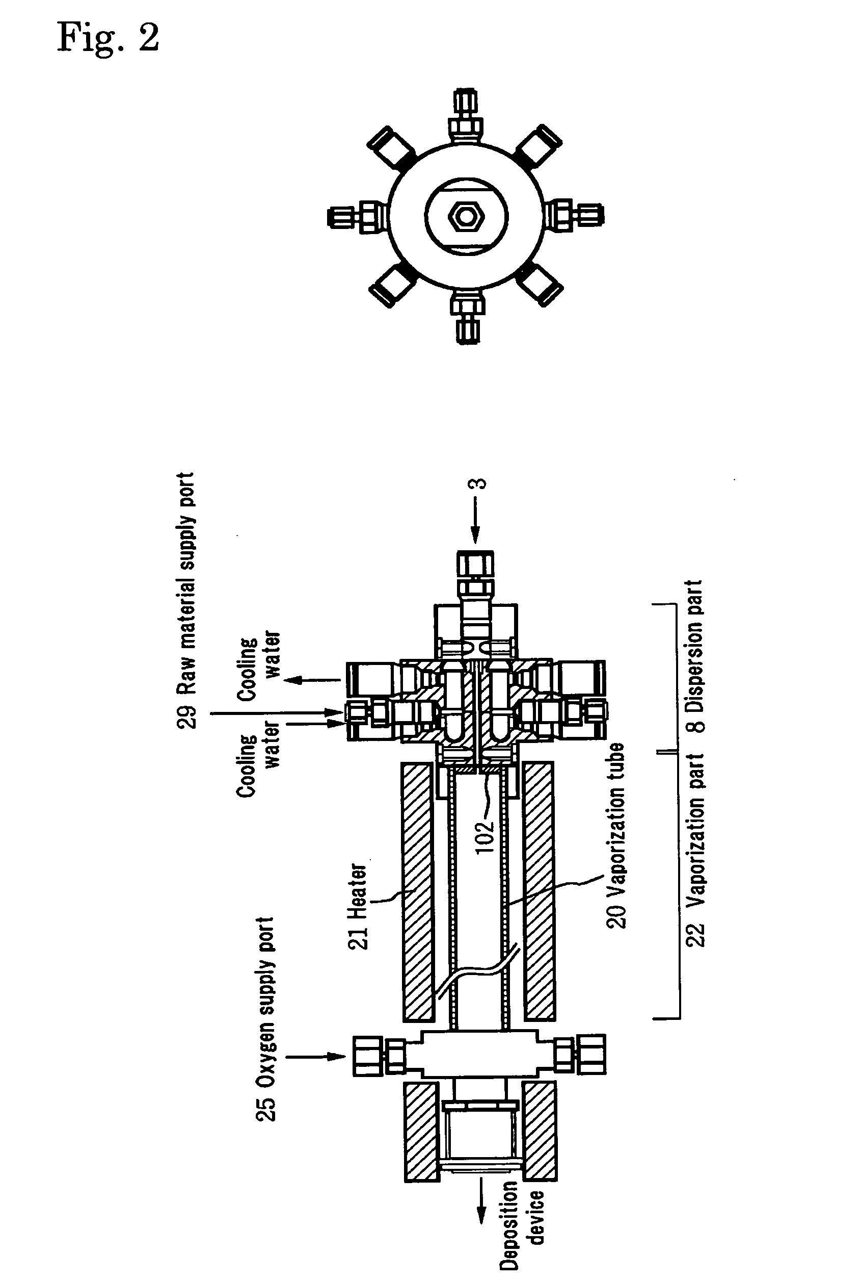
[0166]FIG. 1 shows a vaporizer for MOCVD according to an embodiment 1.

[0167]This embodiment includes a dispersion part 8 including a gas passage 2 formed in the interior of a dispersion main body 1 constituting the dispersion part, a gas inlet 4 to introduce a pressurized carrier gas 3 into the gas passage 2, a means (a raw material supply hole) 6 to supply a raw material solution 5 to the carrier gas 3 passing through the gas passage 2 and atomize the raw material solution 5, a gas outlet 7 to send the carrier gas (raw material gas) including the atomized raw material solution 5 to a vaporization part 22, and a means (cooling water) 18 to cool the carrier gas flowing in the gas passage 2. The embodiment further includes the vaporization part 22 for heating the carrier gas and the raw material solution to be dispersed and vaporizing the raw material solution, sent from the dispersion part 8, the vaporization part including a vaporization tube 20 whose one end is connected to a react...

embodiment 2

[0198]FIG. 5 shows the vaporizer for MOCVD according to the embodiment 2.

[0199]In this embodiment, a cooling water passage 106 was formed around the outer periphery of the radiation prevention part 102, and cooling means 50 was installed around the outer periphery of a connection part 23, and radiation prevention part 102 was cooled. Moreover, a hollow 107 was installed around the outlet of the small hole 101.

[0200]Other aspects were made similar to the embodiment 1.

[0201]In this embodiment, the detected product agrees better with the product in the reaction formula that had been examined based on the reaction theory than that of the embodiment 1. Moreover, the amount of adhesion of the carbide was about ⅓ times of the case of the embodiment 1, as determined from the measurement of the amount of adhesion of the carbide of on the outer surface on the gas outlet 7 side of the dispersion main body 1.

embodiment 3

[0202]FIG. 6 shows the vaporizer for MOCVD according to the embodiment 3.

[0203]In this embodiment, taper 51 is installed in radiation prevention part 102. The dead zone in the concerned part disappears because of this taper 51, and the stagnation of raw material can be prevented.

[0204]Other aspects were made similar to the embodiment 2.

[0205]In this embodiment, the detected product agrees better with the product in the reaction formula that had been examined based on the reaction theory than that of the embodiment 2. Moreover, the amount of adhesion of the carbide was almost null, as determined from the measurement of the amount of adhesion of the carbide of on the outer surface on the gas outlet 7 side of the dispersion main body 1.


PUM

PropertyMeasurementUnit
speedaaaaaaaaaa
temperatureaaaaaaaaaa

Abstract

A vaporizer has gas passage formed inside of main body of a dispersion part, a gas inlet opening to introduce pressurized carrier gas into gas passage, a part to supply raw materials solution to carrier gas passing gas passage, a gas outlet to send carrier gas including dispersed raw material solution to vaporization part, a dispersion part to flow through gas passage having a part to cool, a vaporization pipe connected with a reaction part and gas outlet of dispersion part of the device, and a heater to heat vaporization pipe is provided, a vaporization part to heat and vaporizes the carrier gas where raw materials solution is dispersed is provided, and a radiation prevention portion having small hole for the outside of gas outlet is provided.

Description

BACKGROUND OF THE INVENTION[0001]1. Technical Field[0002]The present invention relates to a vaporizer and a vaporizing method, which is preferably used for a deposition device such as a MOCVD, as well as a other various devices.[0003]2. Background Art[0004]The development of DRAM causes a problem concerning memory capacitance depending on microfabrication. Some measures for the problem about the memory capacitance is necessary because the degree of performance of the capacitance is required to be the same as the former generation in view of potential software errors. As the measure for the above-described problem, a capacitor area has been increased as follows. A planar structure has been taken as the cell structure up to 1M capacity. However, the three-dimensional structure, called a stack structure or a trench structure, has been taken as the cell structure for 4M or above. Moreover, as a dielectric film, a film which laminates an oxidation film from the heat oxidation film of a S...

Claims


Application Information

Patent Timeline
Patent Type & Authority Applications(United States)
IPC IPC(8): C23C16/44B01B1/00B01D3/34B01F3/04B01F5/06C23C16/40C23C16/448H01L21/02H01L21/316H01L21/8246H01L27/115
CPCB01B1/005Y10S261/65B01F3/04021B01F5/0646B01F5/0653B01F5/0656B01F5/0671B01F5/0676C23C16/40C23C16/409C23C16/4486H01L21/31691H01L27/11502H01L27/11507H01L28/55B01D3/346B01F23/213B01F25/4336B01F25/434B01F25/44163B01F25/44167B01F25/433H01L21/02271H01L21/02197H01L21/02205H10B53/30H10B53/00H01L21/205
Inventor TODA, MASAYUKIKUSUHARA, MASAKIUMEDA, MASARUFUKAGAWA, MITSURU
Owner M WATANABE CO LTD
Why Eureka
Try Eureka