
Anti-fouling apparatus for cleaning deposits in pipes and pipe joints

a technology for anti-fouling apparatus and pipes, which is applied in the direction of cleaning processes and apparatus, cleaning using tools, chemistry apparatus and processes, etc., can solve the problems of reducing the cost of reassembly, affecting the quality of pipe cleaning, and requiring additional cost of direct labor

Active Publication Date: 2013-07-11
ALTERRA ENERGY LLC
View PDF24 Cites 22 Cited by
  • Summary
  • Abstract
  • Description
  • Claims
  • Application Information

AI Technical Summary

Benefits of technology

The present invention is a better way to clean pipes and joints to remove deposits that can damage them and the surfaces they touch. It involves three components that go inside the pipe: an internal mobile component, fixed upper and lower fittings, and a mobile ring with magnets. This allows for controlled movement of the mobile component and magnetic ring, combining the power of magnets with the controlled movement of the mobile wiping component. The system can be used manually or electronically controlled, and can be deployed in straight or curved piping runs, heated or unheated systems, or systems that need to operate continuously.

Problems solved by technology

This condition is especially problematic for continuous processes having pipe connections allowing for discharge from one system component to another, such points of discharge often promoting said condensation and / or deposition of solids where flow rates, flow directions and flow volumes change within the process apparatus.
Without a means for continual and effective in situ removal of said condensates and deposits, which may otherwise accumulate in increasing thickness with time, said industrial process production becomes inefficient because it must be interrupted by costly temporary shutdowns to allow for disassembly of the affected components and either subsequent manual cleaning of pipes and pipe joints with scraping or abrasive cutters, or alternative replacement of the affected parts.
After disassembly for cleaning or replacement of pipes and pipe joints, additional cost of direct labor expense and lost production time is incurred for reassembly, leak testing and, in many cases, the system must be purged of atmospheric air prior to resumption of the process.
When replacement is required, the cost of parts inventory must be considered.
Such continual need for ex situ cleaning can pose opportunity for chronic exposure of workers to airborne hazardous or even poisonous components of condensates and deposits.
Such devices do not allow for movement counter to the fluid flow, and the trip is one-way.
Prior art does not describe means to clean the interior of heated pipes and pipe joints having heating elements on the exterior of the pipes, such heating elements interfering with the operation of an exterior magnetic ring sleeve that cannot advance the interior wiping member past the lengths covered by heating elements.
Accordingly, such heated systems cannot be completely cleaned via prior art, leaving interior accumulating deposits in the pipes and pipe joints which, if left in place, can obstruct the flow through the piping system.
Nor does prior art describe means to specifically and continually eliminate hardening, hardened, turbostratic, crystallizing or crystallized substances from the interior of pipes and pipe joints with an internal movable device.
Accordingly, if the internal movable device is not constantly moving, or engaged to move with only brief intervals between cleaning events, these fouling, hardening, hardened, crystallizing or crystallized substances can accumulate in the interior of the pipes and pipe joints at a rate by which the thickness of these fouling substances can become sufficiently thick, and the resistance to cleaning become sufficiently high, that the internal movable device cannot maintain a clean interior pipe and pipe joint surface, or can become stuck in the pipe altogether, creating a condition which promotes additional fouling, plugging and, potentially, unwanted or dangerous pressure build-up.
Nor does prior art provide a solution to cleaning of the anti-fouling apparatus itself.
Nor does prior art describe a means to counteract the phenomenon of preferential or accelerated deposition of fouling deposits at points where material flow velocities change within the piping run.

Method used


Image

  • Anti-fouling apparatus for cleaning deposits in pipes and pipe joints
  • Anti-fouling apparatus for cleaning deposits in pipes and pipe joints
  • Anti-fouling apparatus for cleaning deposits in pipes and pipe joints

Examples


Embodiment Construction

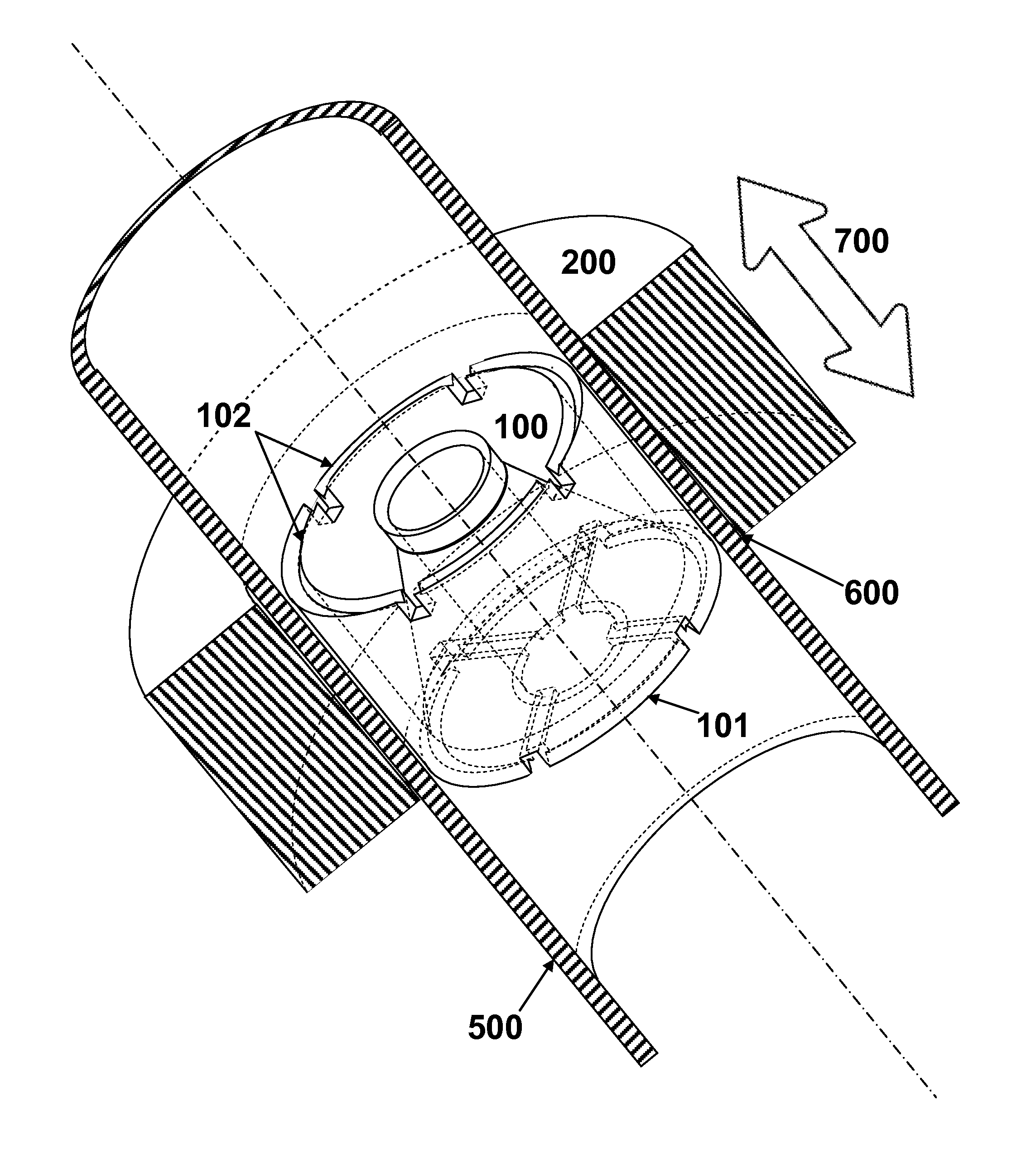
[0018]The present invention provides a means for cleaning the interior of pipes and pipe joints in industrial apparatus impacted by fouling deposits, such as particles or liquids that are entrained in the gas or vapor exiting a piece of equipment. The particles and / or liquids can accumulate in flow lines and points of vapor transfer. By periodically or continuously cleaning while the industrial apparatus continues to run, the apparatus is allowed to operate without significant interruption or need the extensive cleaning that is necessitated by a larger build-up.

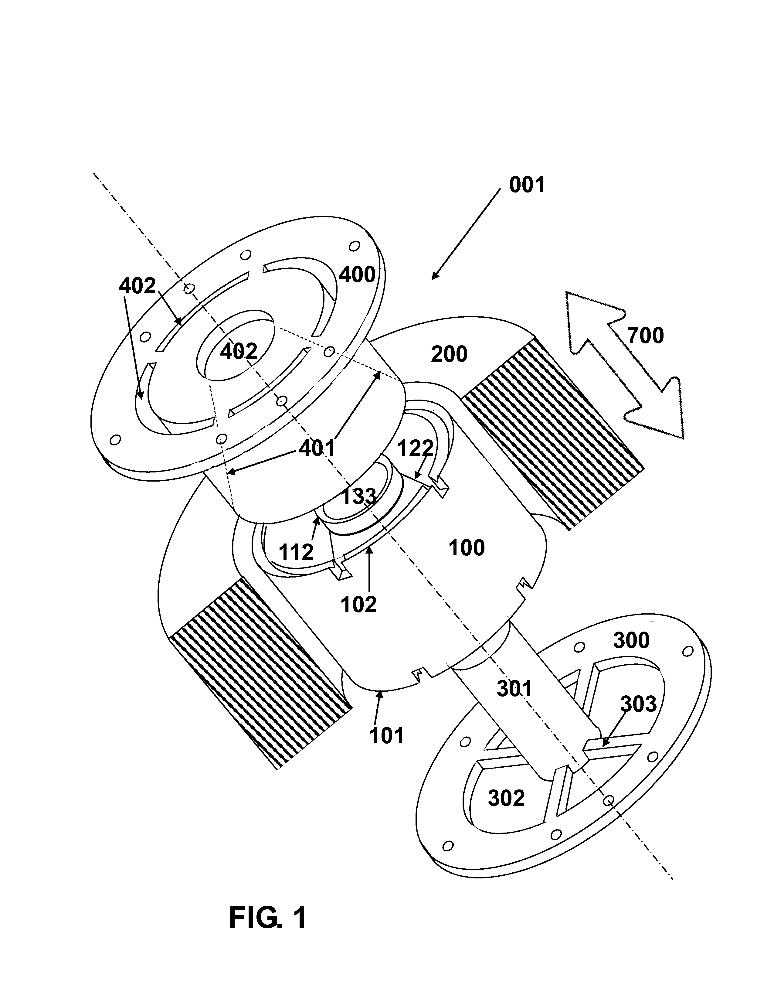
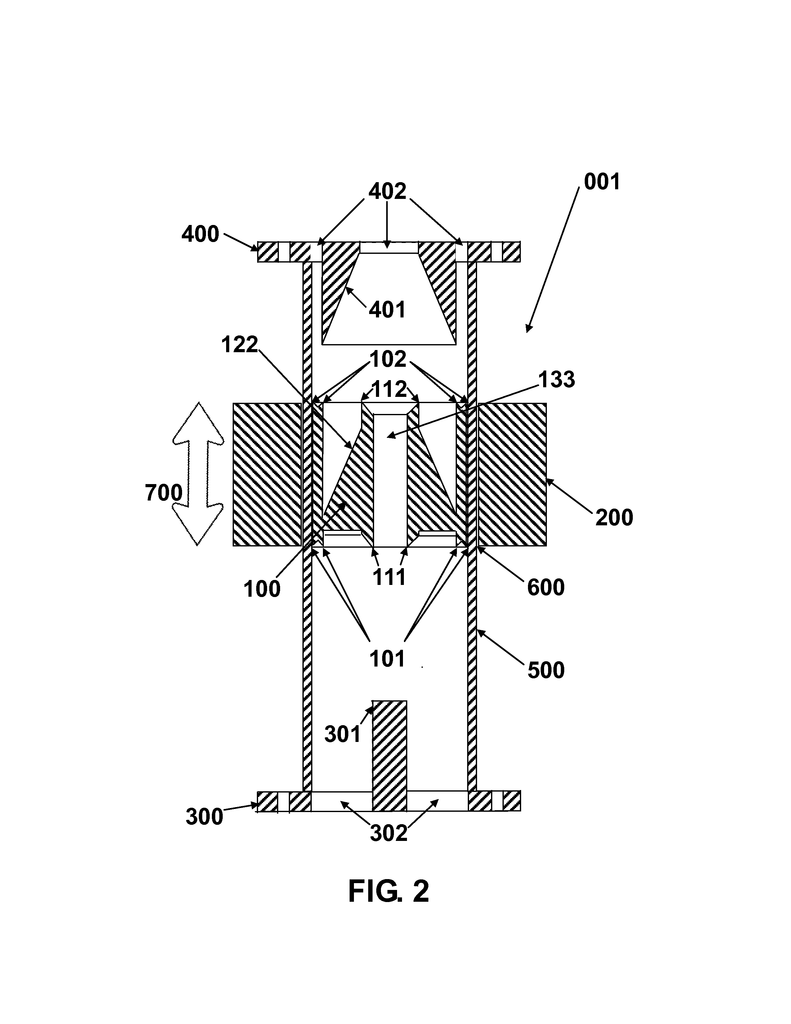
[0019]The present invention is a four-component cleaning assembly, including three internal components plus one external component. An internal wiping component or member is in mating relationship with a pipe interior and it is moved to corresponding special upper and lower pipe flanges as well as the internal wall of the pipe. The internal wiping component is a cylindrical cleaning body that moves within the pipe. Such a cle...


PUM


Abstract

A system for cleaning pipes and pipe joints where the interior surface of the pipe becomes coated with material being processed comprising a cylindrical cleaning body having opposing first and second ends, said cylindrical body having an annular shape with interior and exterior walls so that the outer wall contacts the interior surface of a pipe and wherein ends of the cleaning body have means for removing material deposited on the interior surface, a means for moving the apparatus along the length of said pipe, a first and second means for cleaning said cleaning body having passages that allow fluid to pass through, wherein said first and second cleaning means mates with said first and second ends of said cleaning body, where said cleaning body is moved into contact with said cleaning means to dislodge accumulated deposits from the cleaning body and simultaneously dislodging accumulated deposits from said cleaning means.

Description

BACKGROUND OF THE INVENTION[0001]The present invention is directed to an improved pipe cleaning assembly. More specifically, the present invention provides means for periodic or continuous cleaning of pipes and pipe joints in industrial apparatus such as those experiencing deposition of mineral and / or organic solids onto their interior surfaces and those having a condensation zone or outlet to a condensation pipe either alone or combined with reflux condensation where the condensation step is prone to accumulation of deposits on the interior surfaces of the pipes and pipe joints carrying gases with entrained aerosols and / or particulate matter that are subject to deposition and / or condensation.[0002]Certain industrial processes, including but not limited to pyrolysis, petrochemical, metallization and semi-conductor processes, produce vapor streams containing nanoparticles and microparticles which tend to condense and / or otherwise deposit on the interior walls of pipes and pipe joints...

Claims


Application Information

Patent Timeline
IPC IPC(8): F16L55/28B08B9/055
CPCF16L55/28B08B9/0436B08B9/0553
Inventor ULLOM, WILLIAM L.
Owner ALTERRA ENERGY LLC
Features
  • Generate Ideas
  • Intellectual Property
  • Life Sciences
  • Materials
  • Tech Scout
  • Unparalleled Data Quality
  • Higher Quality Content
  • 60% Fewer Hallucinations
Learn More